Dual Gradient Drilling Method And Apparatus With An Adjustable Centrifuge

a centrifuge and adjustable technology, applied in the direction of chemistry apparatus and processes, borehole/well accessories, construction, etc., can solve the problems of mud density dropping and becoming so light that a kick occurs, threat to drilling operations, and significant risk to both drilling personnel and the environmen

Inactive Publication Date: 2008-12-11
DUAL GRADIENT SYST
View PDF26 Cites 76 Cited by
  • Summary
  • Abstract
  • Description
  • Claims
  • Application Information

AI Technical Summary

Problems solved by technology

This is further complicated when drilling in deep water or ultra deep water because of the pressure on the sea floor by the water above it.
When the mud density is insufficient, the gases or fluids in the borehole can cause the mud to decrease in density and become so light that a kick occurs.
Kicks are a threat to drilling operations and a significant risk to both drilling personnel and the environment.
However, the primary method for minimizing the risk of a blowout condition is the proper balancing of the drilling mud density to maintain the well in a balanced condition at all times. While BOP's can contain a kick and prevent a blowout from occurring thereby minimizing the damage to personnel and the environment, the well is usually lost once a kick occurs, even if contained.
While this is desirable, it unfortunately slows down the drilling process.
In some cases underbalanced drilling has been attempted in order to increase the drilling rate.
Deep water and ultra deep water drilling has its own set of problems coupled with the need to provide a high density drilling mud in a wellbore that starts several thousand feet below sea level.
This system is expensive to install, as it requires separate lines, expensive to maintain, and very expensive to run.
While it has been proven desirable to reduce drilling mud density at a location near and below the seabed in a wellbore, there are no prior art techniques that effectively accomplish this objective.

Method used


Image

  • Dual Gradient Drilling Method And Apparatus With An Adjustable Centrifuge
  • Dual Gradient Drilling Method And Apparatus With An Adjustable Centrifuge
  • Dual Gradient Drilling Method And Apparatus With An Adjustable Centrifuge

Examples


Embodiment Construction

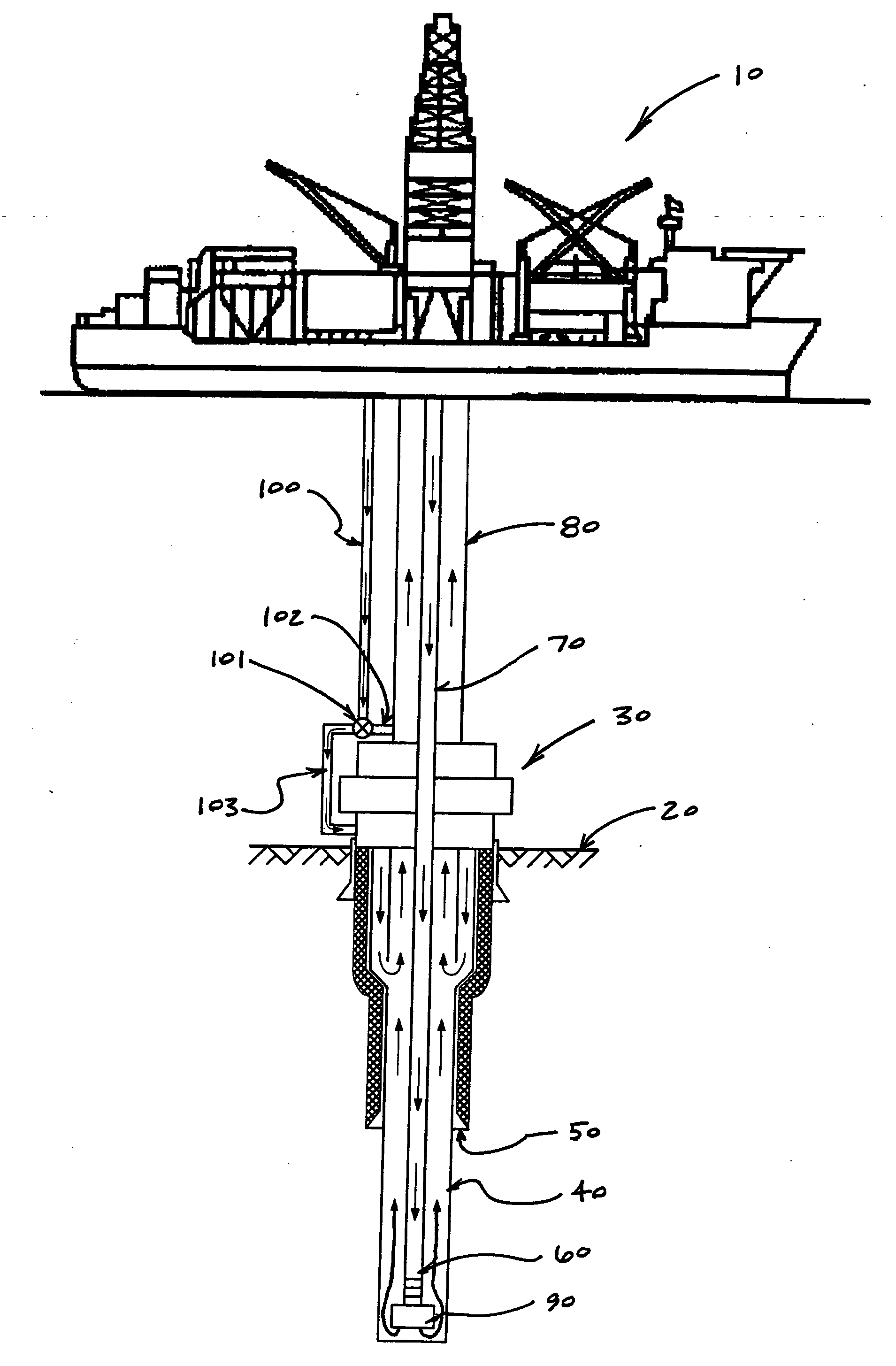
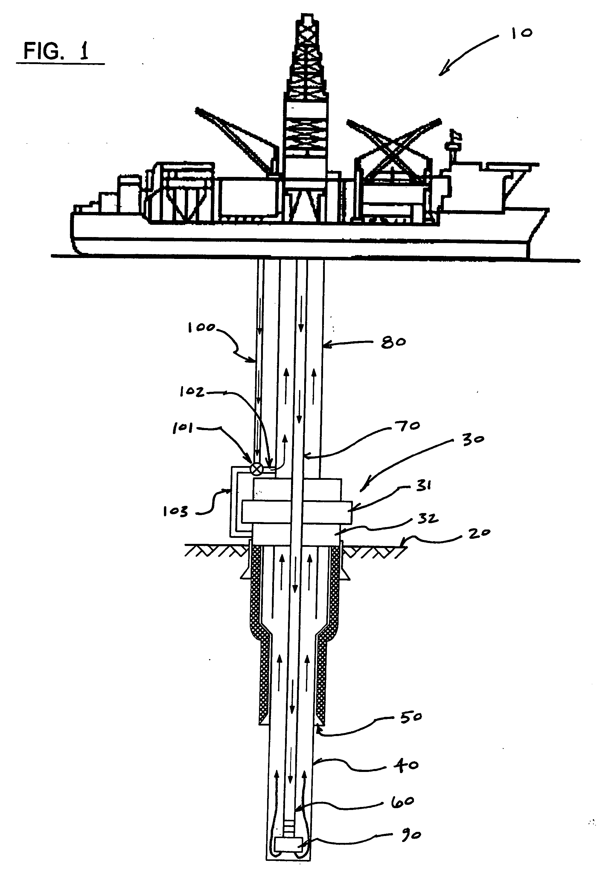
[0051]A description of certain embodiments of the mud recirculation system of the present invention is provided to facilitate an understanding of the invention. This description is intended to be illustrative and not limiting of the present invention. These and other objects, features, and advantages of the present invention will become apparent after a review of the entire detailed description, the disclosed embodiments, and the appended claims. As will be appreciated by one of ordinary skill in the art, many other beneficial results and applications can be appreciated by applying modifications to the invention as disclosed. Such modifications are within the scope of the claims appended hereto.

[0052]Moreover, while the mud recirculation system of the present invention is described with respect to casing installation operations, it is intended that the present invention may be used to install any tubular good used in both conventional and non-conventional well drilling operations in...


PUM


Abstract

A method and system for controlling drilling mud density in drilling operations. The mud required at the wellhead is combined with a base fluid of a different density to produce diluted mud in the riser. By combining the appropriate quantities of drilling mud with base fluid, riser mud density at or near the density of seawater may be achieved, thereby permitting greater control over the pressure in the wellbore and various risers. Blowout preventers may also be used in combination with the process to control these pressures. Concentric risers are disclosed, wherein an annulus defined within one riser is utilized to carry the different density base fluid to the injection point for injection into the drilling mud, while an annulus defined within another riser is utilized to carry the combination fluid and cuttings back to the drilling rig. Cuttings are separated in the usual manner at the surface. The diluted mud is passed through a centrifuge system to separate drilling mud from the different density base fluid. The centrifuge system may also be utilized to separate the recovered drilling fluid into a substantially barite portion and a substantially drilling fluid portion, wherein the two portions are stored locally at the rig and recirculated during drilling operations.

Description

CROSS-REFERENCE TO RELATED APPLICATIONS[0001]The present application is a continuation-in-part of U.S. Pat. No. 6,966,392 issued on Nov. 22, 2005, which is a continuation-in-part of U.S. patent application Ser. No. 10 / 390,528 filed on Mar. 17, 2003, which is a continuation-in-part of U.S. patent application Ser. No. 10 / 289,505 filed on Nov. 6, 2002, which is a continuation-in-part of U.S. patent application Ser. No. 09 / 784,367 filed on Feb. 15, 2001, now U.S. Pat. No. 6,536,540.BACKGROUND OF THE INVENTION[0002]1. Field of the Invention[0003]The subject invention is generally related to systems for delivering drilling fluid (or “drilling mud”) for oil and gas drilling applications and is specifically directed to a method and apparatus for varying the density of drilling mud in deep water oil and gas drilling applications.[0004]2. Description of the Prior Art[0005]It is well known to use drilling mud to provide hydraulic horse power for operating drill bits, to maintain hydrostatic pr...

Claims


Application Information

Patent Timeline
Patent Type & Authority Applications(United States)
IPC IPC(8): E21B21/08E21B21/06
CPCE21B21/001E21B21/063E21B2021/006E21B21/106E21B21/08E21B21/085E21B21/082
Inventor DEBOER, LUC
Owner DUAL GRADIENT SYST
Why Eureka
Try Eureka