

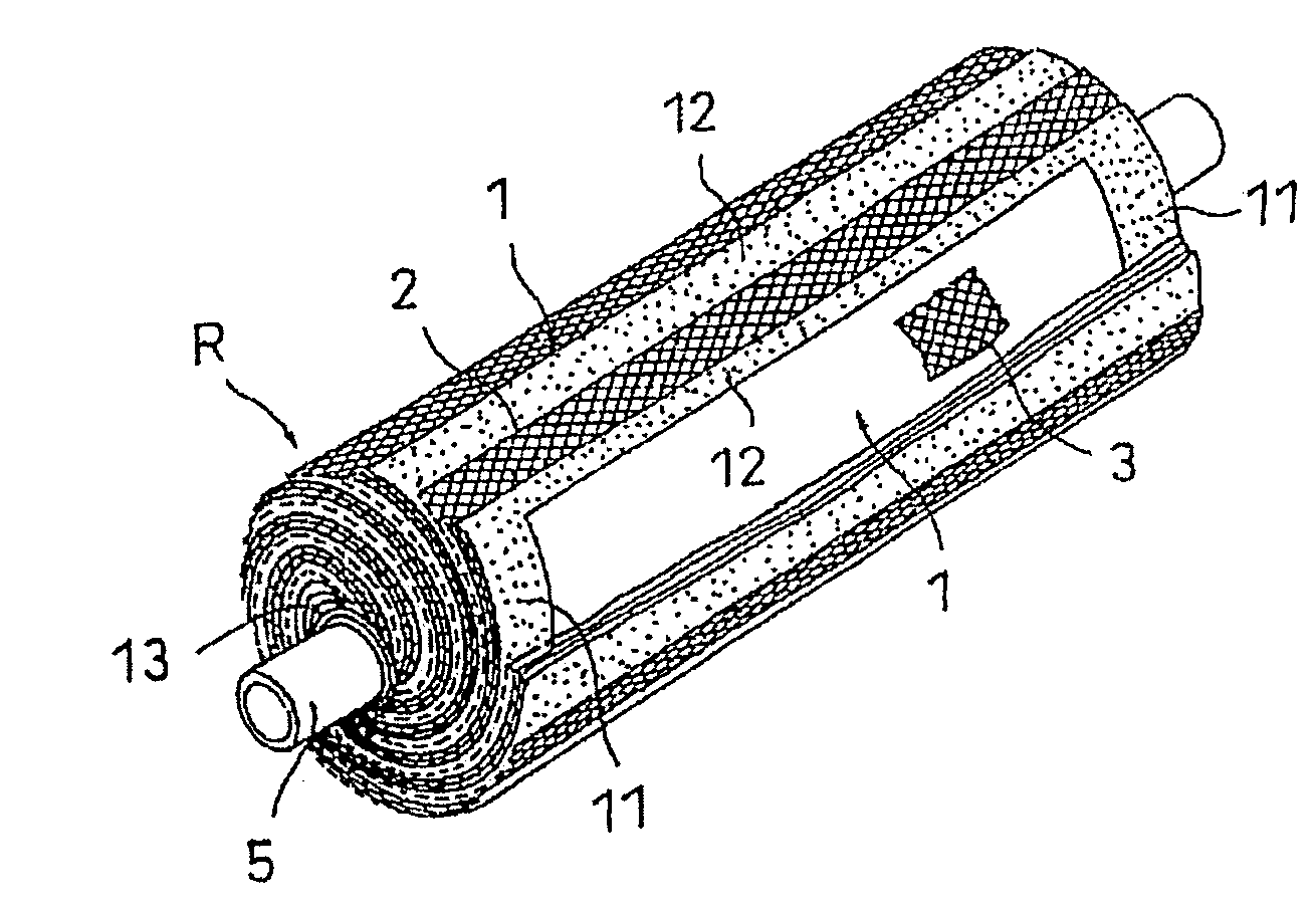
Spiral membrane element and method of producing the same
a technology of spiral membrane element and spiral membrane, which is applied in the direction of filtration separation, separation process, coating, etc., can solve the problem that the spiral cannot be fully fastened, and achieve the effect of reducing the dimension in the length direction of the spiral membrane element, and increasing the strength of the reinforcing fiber layer
- Summary
- Abstract
- Description
- Claims
- Application Information
AI Technical Summary
Benefits of technology
Problems solved by technology
Method used
Image

Examples
embodiment 1
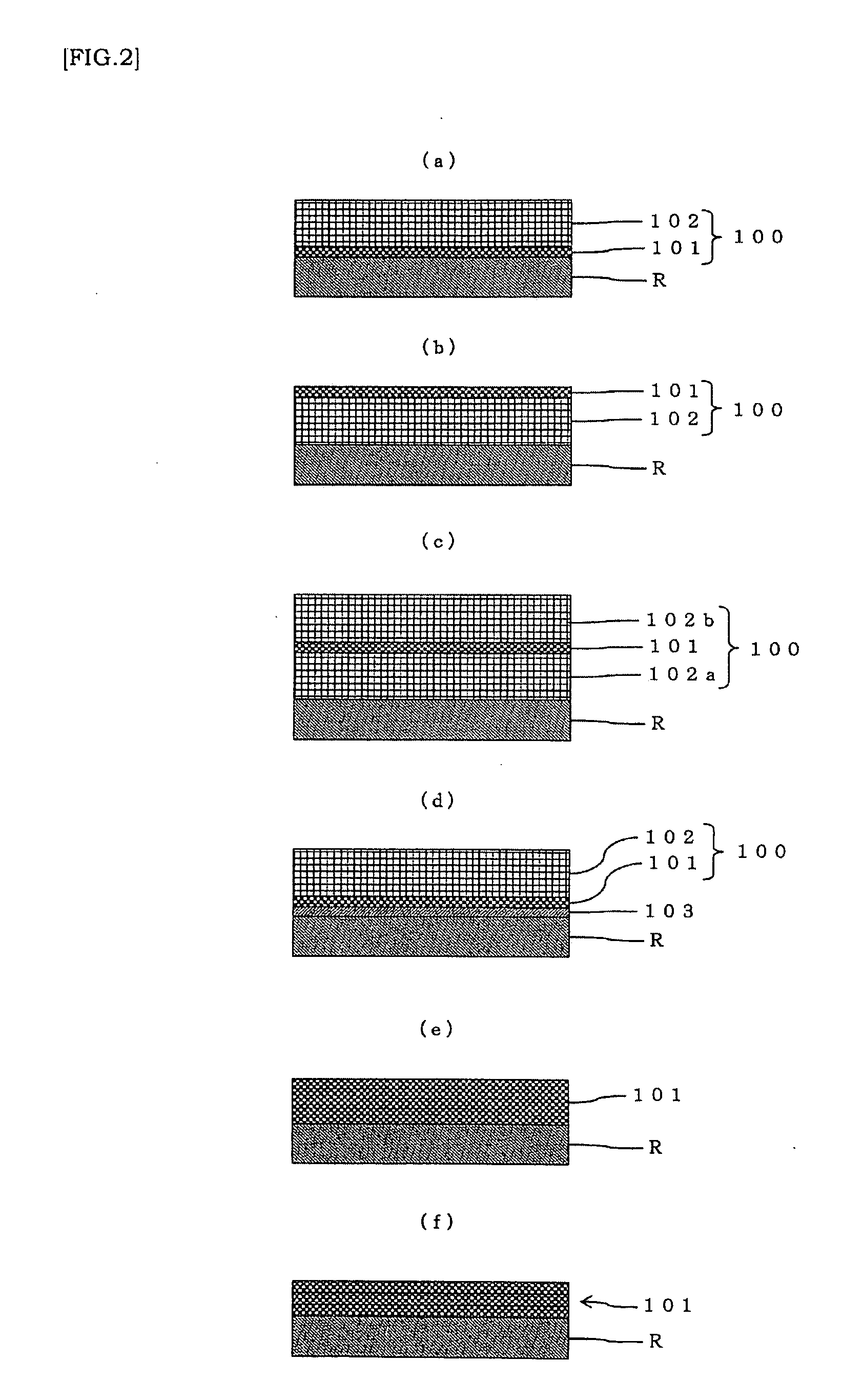
[0056]In the step of forming the fiber reinforced resin layer, after a reinforcing fiber layer (for example, glass cloth) is formed as an inner layer on the outer circumferential side of a cylindrical wound body (for example, after glass cloth having a planar shape is wound therearound for one to several times), the fibers (for example, glass roving) immediately after attachment and / or impregnation of a resin (for example, epoxy resin) are wound in a spiral form without a gap so as to cover the outer circumferential side of the reinforcing fiber layer so as to form a strengthening fiber layer as an outer layer. Preferably, the fibers (glass cloth fibers) of the reinforcing fiber layer are arranged to traverse longitudinally over the entire length relative to the length direction of the cylindrical wound body.
[0057]At this time, it is necessary to provide a step of attaching a resin (epoxy resin) to the fibers (glass roving) and / or impregnating the fibers (glass roving) with the resi...
embodiment 2
[0060]In the step of forming the fiber reinforced resin layer, the fibers (for example, glass roving) immediately after attachment and / or impregnation of a resin (for example, epoxy resin) are wound in a spiral form without a gap so as to cover the outer circumferential side of a cylindrical wound body so as to form a strengthening fiber layer as an outer layer. Immediately after forming the strengthening fiber layer (before curing), a reinforcing fiber layer (glass cloth) is formed as an outer layer.
[0061]The resin (epoxy resin) attached to or subjected to impregnation of the fibers (glass roving) penetrates into a gap between the fibers or into the fibers of the reinforcing fiber layer (glass cloth) and is cured.
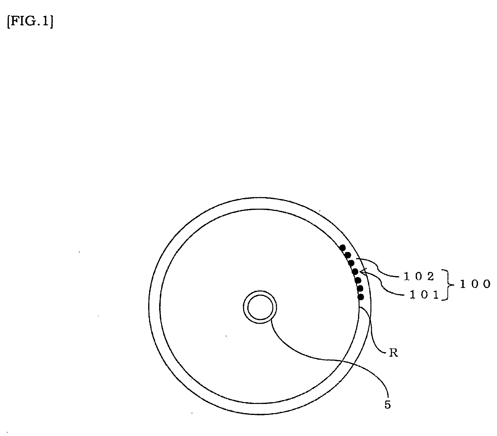
[0062]FIG. 2(b) shows a model view of a constitution example of a cylindrical wound body R / strengthening fiber layer 102 (inner layer) / reinforcing fiber layer 101 (outer layer) formed by the above-described method. The combined thickness of the cylindrical wound body R / str...
embodiment 3
[0063]In the step of forming the fiber reinforced resin layer, the fibers (for example, glass roving) immediately after attachment and / or impregnation of a resin (for example, epoxy resin) (before curing) are wound without a gap so as to cover the outer circumferential side of a cylindrical wound body so as to form a first strengthening fiber layer. Subsequently, immediately after the step of forming the first strengthening fiber layer (before curing), a reinforcing fiber layer (for example, winding a glass cloth) is formed. During this time, the resin (epoxy resin) attached to or subjected to impregnation of the fibers (glass roving) penetrates into a gap between the fibers or into the fibers of the reinforcing fiber layer (glass cloth) and is cured.
[0064]However, after curing, before curing, or before curing completely (after the step of forming the reinforcing fiber layer), the fibers (glass roving) immediately after attachment and / or impregnation of a resin (epoxy resin) are wou...
PUM
| Property | Measurement | Unit |
|---|---|---|
| thickness | aaaaa | aaaaa |
| thickness | aaaaa | aaaaa |
| thickness | aaaaa | aaaaa |
Abstract
Description
Claims
Application Information