Triangular wave generator

Inactive Publication Date: 2008-12-11
RENESAS ELECTRONICS CORP
View PDF6 Cites 10 Cited by
  • Summary
  • Abstract
  • Description
  • Claims
  • Application Information

AI Technical Summary

Benefits of technology

[0016]With the technology of the present invention, in a case of generating two phased triangular waves with phases opposite to each other, it is possible to maintain a constant frequency and a constant crest value of each of the two triangular waves.

Problems solved by technology

However, power supply voltages or currents required by the functional blocks are different from each other.
Accordingly, in a case of supplying power to those functional blocks by using a single chip, when control thereof is performed with a single triangular wave as a reference, there is a limit to an increase in efficiency and a reduction in size of peripheral parts.

Method used


Image

  • Triangular wave generator
  • Triangular wave generator
  • Triangular wave generator

Examples


first embodiment

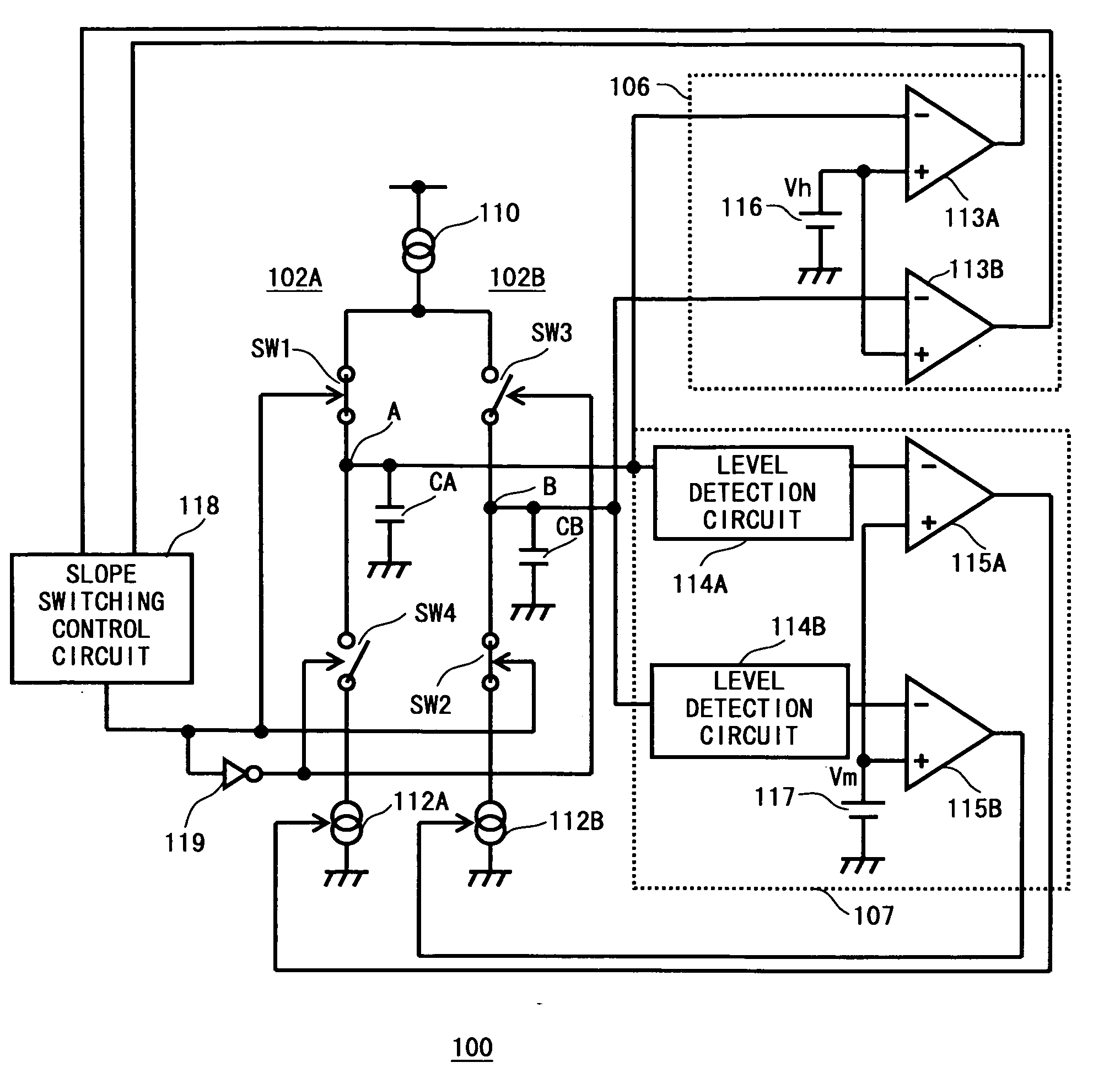
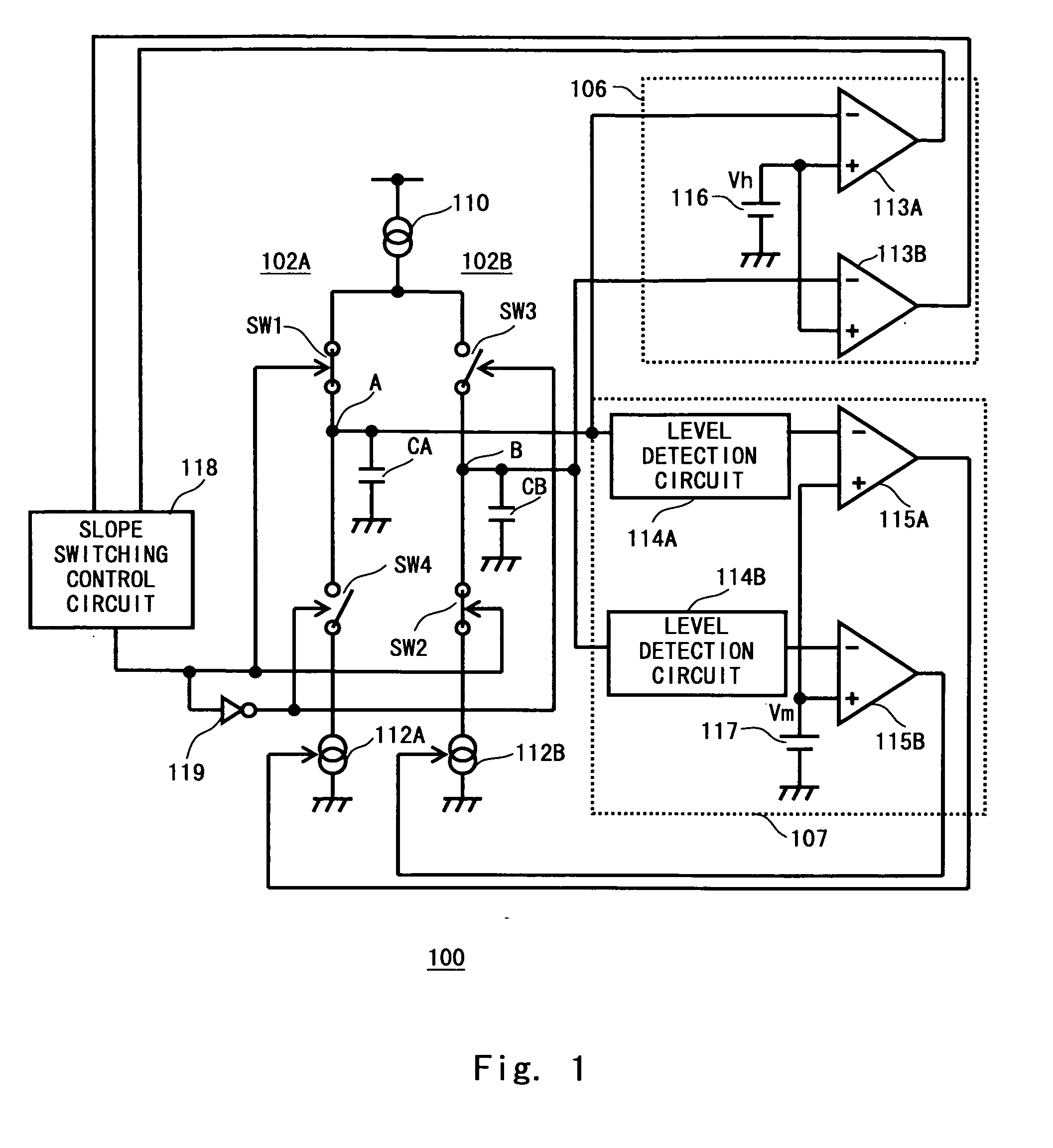
[0033]FIG. 1 shows a triangular wave generator 100 according to a first embodiment of the present invention. The triangular wave generator 100 includes: a first triangular wave oscillation circuit 102A; a second triangular wave oscillation circuit 102B; an output voltage monitoring circuit 106 for monitoring an output voltage of each of the triangular wave oscillation circuits 102A and 102B to detect whether each output voltage reaches a reference upper limit crest value (which corresponds to high level represented by Vh of FIG. 1); a slope switching control circuit 118 for controlling switching of an output voltage generation mode of each of the first triangular wave oscillation circuit 102A and the second triangular wave oscillation circuit 102B according to an output of the output voltage monitoring circuit 106; an inverter 119 for inverting signals from the slope switching control circuit 118; and an oscillation level control circuit 107 for controlling an oscillation level of e...

second embodiment

[0095]FIG. 10 shows a triangular wave generator 200 according to a second embodiment of the present invention. Components of the triangular wave generator 200 are similar to the corresponding components of the triangular wave generator 100 except that an output voltage monitoring circuit 206 of the triangular wave generator 200 is different from the output voltage monitoring circuit 106 of the triangular wave generator 100. In FIG. 10, the components having the configuration similar to those of the triangular wave generator 100 are denoted by the same reference symbols, and detailed description thereof is omitted.

[0096]As shown in FIG. 10, the output voltage monitoring circuit 206 includes a switch SW5, a reference voltage source 116 for supplying the reference upper limit crest value, that is, the high level Vh, and a comparator circuit 213. The switch SW5 inputs one of the A-wave and the B-wave, which has the up-slope waveform, to the comparator circuit 213. Specifically, when the...


PUM


Abstract

Triangular wave oscillation circuits generate A-wave and B-wave with phases opposite to each other, and are capable of independently controlling oscillation levels of the A-wave and the B-wave. A slope switching circuit including an output voltage monitoring circuit, a slope switching control circuit, and an inverter, monitors output voltages of the triangular wave oscillation circuits, to switch an output voltage generation mode of one triangular wave oscillation circuit whose triangular wave reaches a high level, from an up-slope waveform mode to a down-slope waveform mode, and to switch an output voltage generation mode of the other triangular wave oscillation circuit, from the down-slope waveform mode to the up-slope waveform mode. An oscillation level control circuit controls an oscillation level of the other triangular wave oscillation circuit so that the output voltage of the other of the triangular wave oscillation circuit becomes a reference lower limit crest value during the switching.

Description

BACKGROUND OF THE INVENTION[0001]1. Field of the Invention[0002]The present invention relates to a technology of generating triangular waves, and more particularly, to a technology of generating two phased triangular waves with phases opposite to each other.[0003]2. Description of Related Art[0004]Up to now, a switching regulator is often used for a device incorporating a single high-current power supply, such as a television device or a personal computer. In recent years, along with a demand for a reduction in size, a prolonged battery life, or the like of a mobile device, the switching regulator is generally implemented in the mobile device, and functional blocks such as a CPU, a memory, and a display panel are supplied with power using a single chip.[0005]However, power supply voltages or currents required by the functional blocks are different from each other. Accordingly, in a case of supplying power to those functional blocks by using a single chip, when control thereof is per...

Claims


Application Information

Patent Timeline
IPC IPC(8): H03K4/06
CPCH03K3/0231H03K4/06
Inventor KUBO, NARIHIRO
Owner RENESAS ELECTRONICS CORP
Why Eureka
Try Eureka