Eureka AIR delivers breakthrough ideas for toughest innovation challenges, trusted by R&D personnel around the world.

Integrated multi-beam antenna receiving system with improved signal distribution

a multi-beam antenna and receiving system technology, applied in the direction of antennas, antenna details, electrical equipment, etc., can solve the problems of reducing the number of odu components, affecting the frequency plan, and affecting the implementation of mixed ku bss/fss systems, etc., to achieve the effect of reducing the number and complexity of odu components

Inactive Publication Date: 2008-12-11
ORR PARTNERS I +1
View PDF71 Cites 10 Cited by
  • Summary
  • Abstract
  • Description
  • Claims
  • Application Information

AI Technical Summary

Benefits of technology

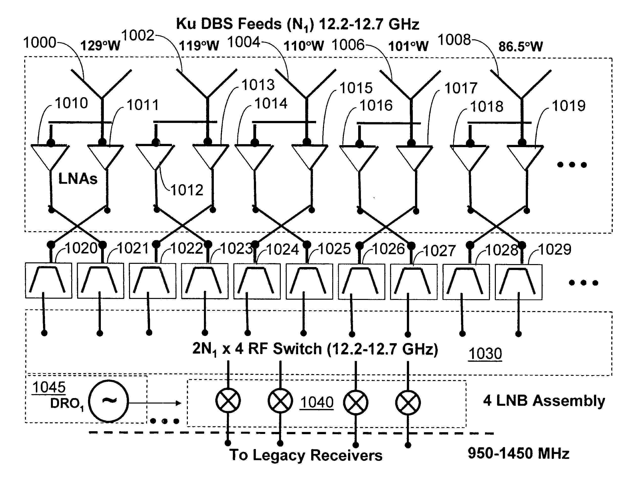
[0019]To minimize the limitations of the prior art, and to minimize other limitations that will become apparent upon reading and understanding the present specification, the present invention discloses a method and apparatus for an integrated multi-beam satellite receiving system which can accommodate future orbital assets without changes to the physical infrastructure installed. The present invention can also accommodate a single coaxial cable delivery of multiple satellite signals to the home for new users. It can further minimize the number and complexity of ODU components by delivering only the desired transponders selected by the IRDs rather than the present method which delivers the total bandwidth of all orbital assets to each IRD.

Problems solved by technology

Bandwidth and other limitations prevent the use of more than one Ku FSS satellite at a time in conjunction with the Ku DBS satellites of this configuration.
Since the polarization varies as the selected satellite varies across the geostationary arc, it is obvious that this severe limitation greatly complicates the implementation of the mixed Ku BSS / FSS system.
In addition, the incorporation of future satellites operating in the Ka BSS band (17.2-17.7 GHz) cannot be accommodated by the frequency plan of FIG. 5.

Method used


Image

  • Integrated multi-beam antenna receiving system with improved signal distribution
  • Integrated multi-beam antenna receiving system with improved signal distribution
  • Integrated multi-beam antenna receiving system with improved signal distribution

Examples


Embodiment Construction

Overview

[0038]In the following description, reference is made to the accompanying drawings which show, by way of illustration, several embodiments of the present invention. It is understood that other embodiments may be utilized without departing from the scope of the present invention.

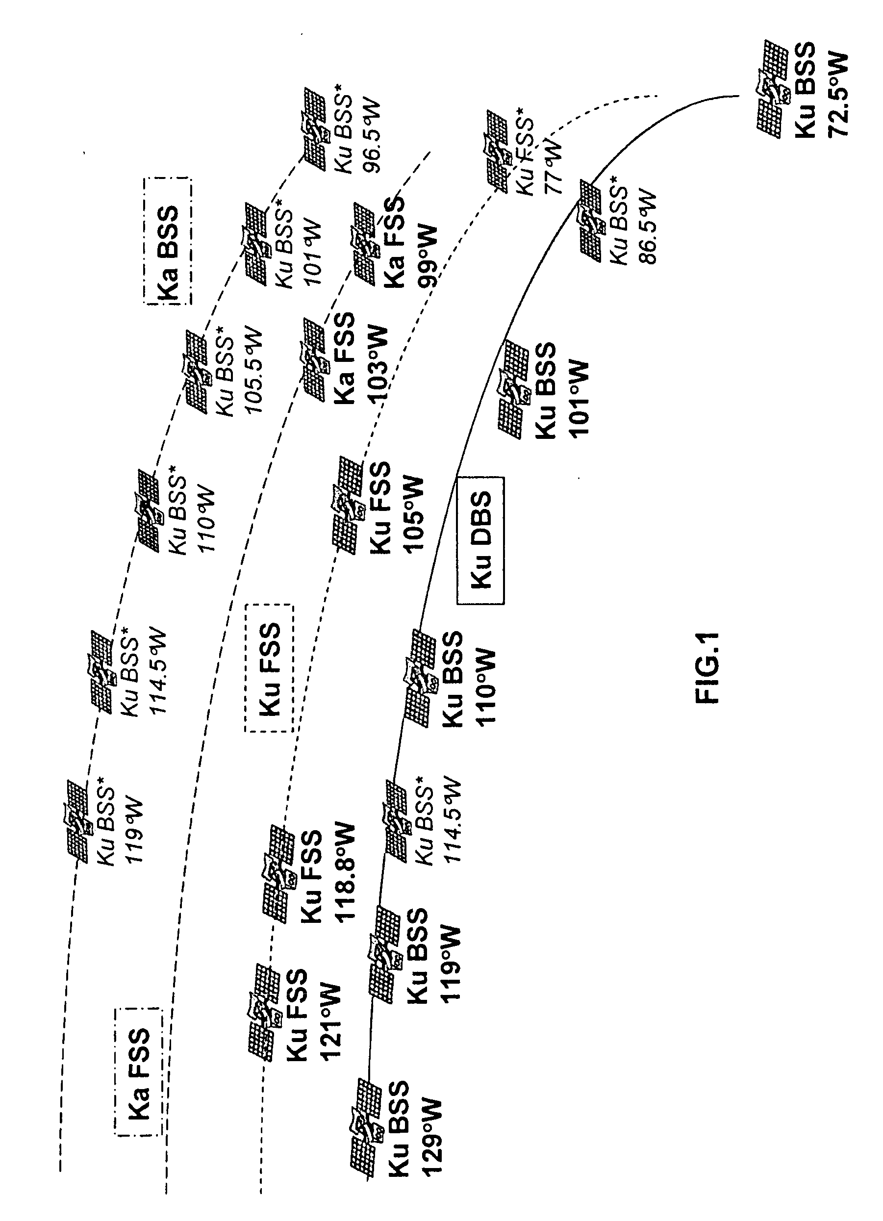
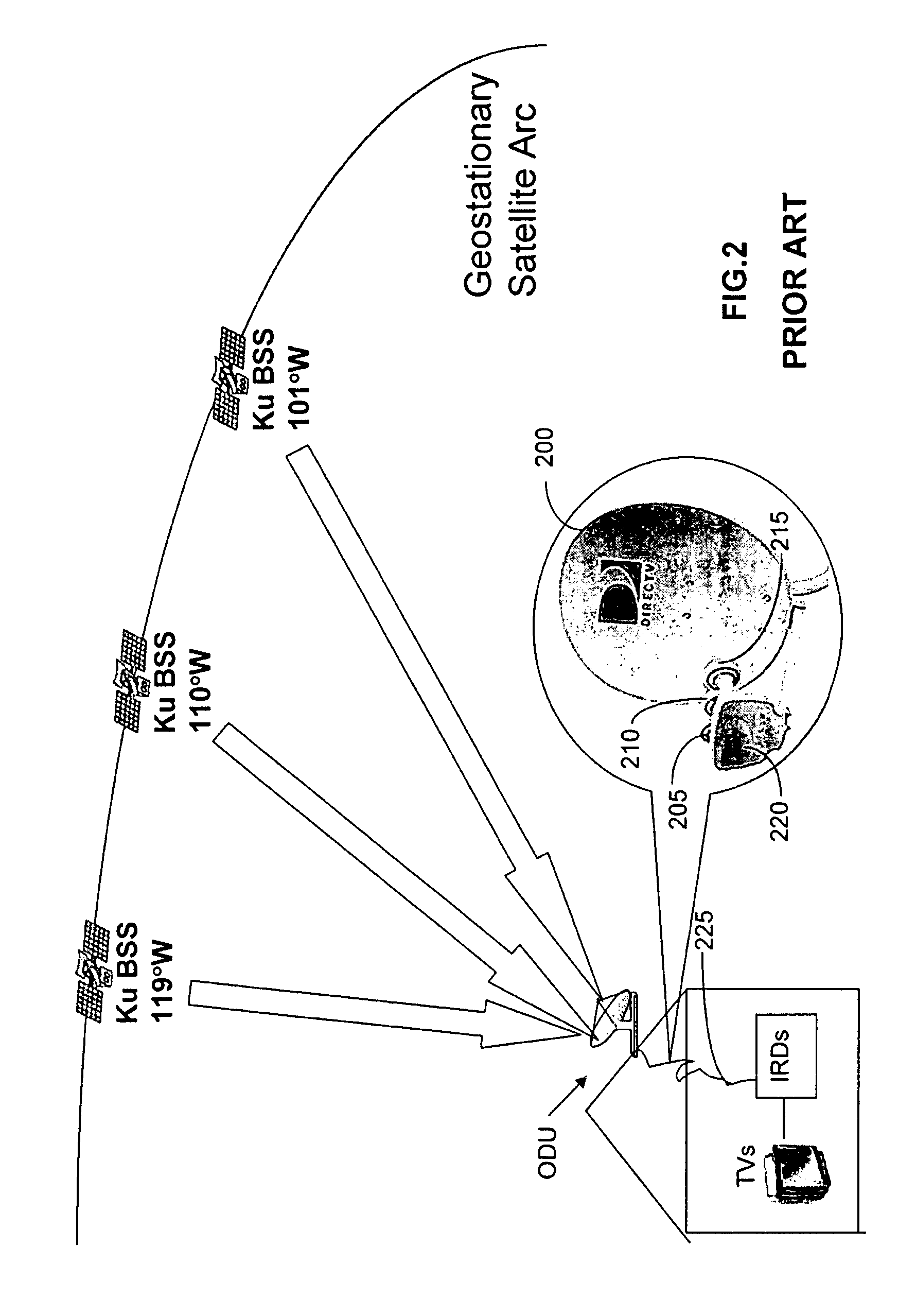
[0039]As illustrated in FIGS. 1-5, there are several architectures employed by the related art to receive satellite signals from direct broadcast satellites and deliver video content into the home. These systems may be categorized as follows: (1) FIG. 2 shows an expanded Ku BSS architecture in which the signals are delivered from up to three orbital locations operating in the original 12.2-12.7 GHz BSS frequency bands. (2) FIG. 3 shows a hybrid Ku BSS / Ka FSS architecture in which the video signals are delivered from three Ku BSS and two Ka FSS orbital locations. (3) FIG. 4 shows a hybrid Ku BSS / Ku FSS architecture in which the video signals are delivered from three Ku BSS and one Ku FSS orbital locati...


PUM


Abstract

An integrated multi-beam antenna receiving system controls signal flow to a set of frequency translation devices in order to provide the required signals requested by Integrated Receiver Decoder units (IRDs, or set-top-boxes) within the home. The receiving system is compatible with legacy IRDs, or can support delivery of the requested signals in digital format allowing single coaxial cable or twisted pair delivery into the home. The system supports satellite reception from a mixed constellation of Direct Broadcast Satellites (DBS) and Fixed Satellite Service platforms operating in multiple frequency bands.

Description

CROSS-REFERENCE TO RELATED APPLICATIONS[0001]This Application claims priority from U.S. Provisional Application Ser. No. 60 / 942,635 filed on Jun. 7, 2007, the entire disclosure of which is incorporated herein by reference.BACKGROUND[0002]1. Field of the Invention[0003]The present invention relates to an integrated antenna and receiving system, consisting of a multi-beam antenna aperture, a low noise receiving system, frequency translation modules, and digital demodulators which provide multiple satellite transponder channels to set-top-boxes within a home.[0004]2. Description of the Related Art[0005]Satellite broadcasting of television programming has evolved from a distribution source consisting of a single Ku-band Direct Broadcasting Satellite (DBS) to multiple satellites operating in both the DBS (officially called BSS) service as well as the systems typically used for two-way satellite communications (FSS). Recently additional satellites operating in higher frequency bands (Ka F...

Claims


Application Information

Patent Timeline
IPC IPC(8): H01Q1/00
CPCH01Q25/007
Inventor SHARON, THOMAS EDWARDHAZIZA, DEDI DAVID
Owner ORR PARTNERS I
Why Eureka
Eureka Blog
Learn More