System and Method of Offloading Protocol Functions
a protocol function and protocol technology, applied in the field of networked communication systems and methods, can solve the problems of difficult bridging between a reliable, ordered switched fabric like rapidioTM and an unreliable, unordered network like ethernet, and achieve the effect of high data ra
- Summary
- Abstract
- Description
- Claims
- Application Information
AI Technical Summary
Benefits of technology
Problems solved by technology
Method used
Image
Examples
example 1
Rapid IO Gateway
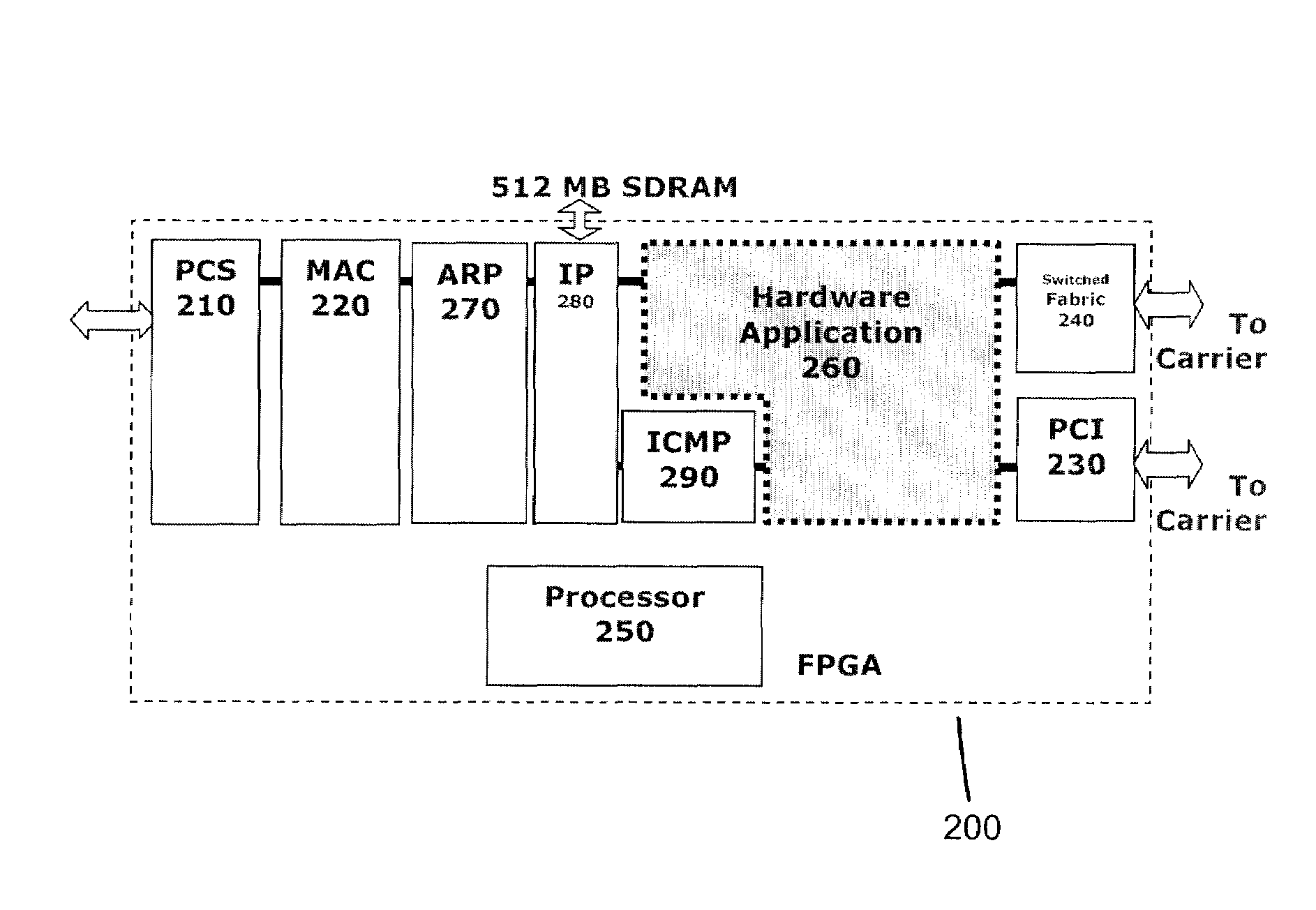
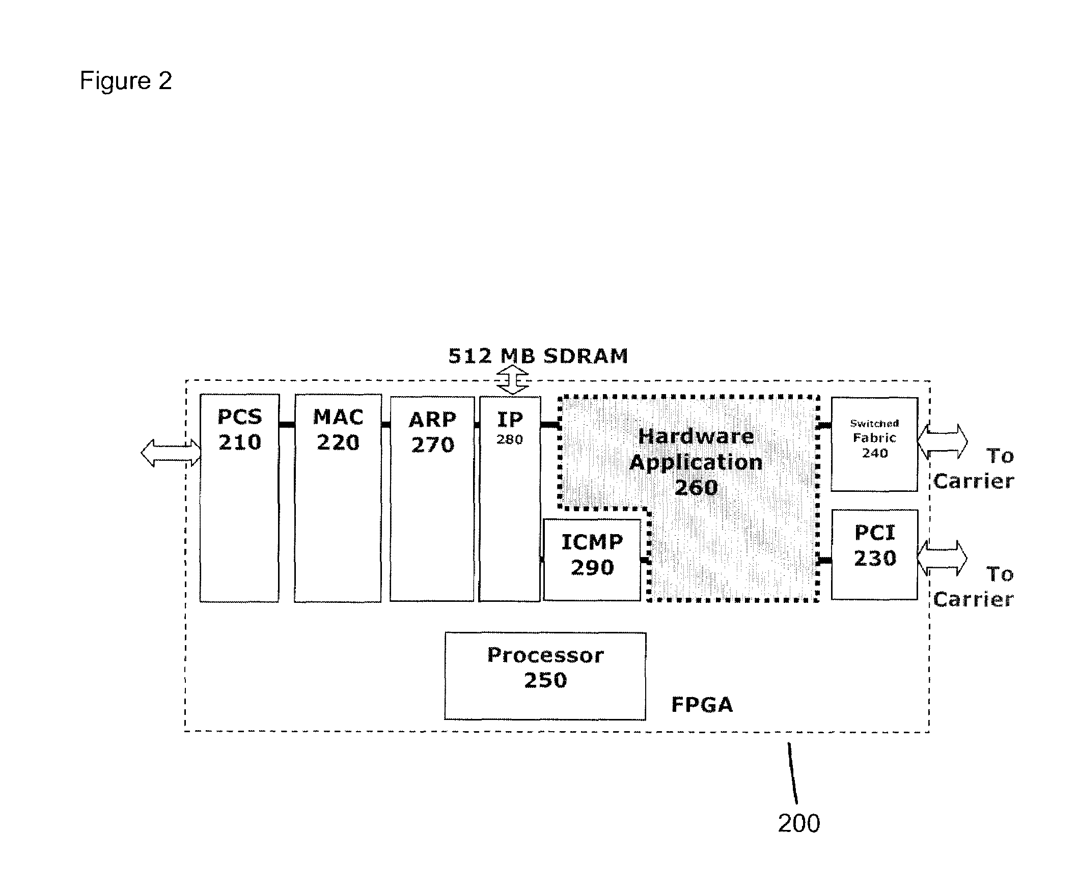
[0040]FIG. 4 shows a typical embedded system configuration with two processing elements all connected through a switched fabric to the offload engine 200 to communicate with IP network 440.
[0041]In this example, each of the processing elements 420 runs its own TCP / IP stack 430 and has its own IP address. The TCP / IP packets are wrapped up into the switched fabric's (in this example RapidIO™410) packets. This is effectively an IP network running over a RapidIO™ switched fabric.
[0042]Hardware application 260 acts as a gateway between the 10 Gbps IP network 440 and the RapidIO™ switched fabric network. Packets coming in from RapidIO™410 have their headers stripped off and the encapsulated IP packet is sent out to the IP sink. IP packets coming in from the IP source are checked against a lookup table which matches destination IP address ranges to RapidIO™ device IDs. The lookup table may be in hardware (for example in FPGA 200) or in software (for example running on proce...
example 2
RapidIO™ Tunneling
[0044]In this example, RapidIO™ packets are encapsulated into UDP packets. Hardware application 260 tracks lost and out-of-order packets and reports these errors to processing elements 420. These errors are treated as catastrophic and may require complete system restarts.
[0045]Offload engine 200 maps ranges of RapidIO™ device IDs to IP addresses using a table set up at system startup. This system allows for interclass communication over an IP network 440 and is completely transparent to the processing elements 420. All legal RapidIO™ packets can be transferred over the network.
[0046]FIG. 5 shows an example RapidIO™ Tunneling system configuration.
example 3
TCP Termination
[0047]In this scheme, the preferred embodiment of the invention, TCP end-points for each processing element (PE) 420 are implemented in hardware application 260 on offload engine 200. Hardware application 260 maintains the state for each TCP connection and takes care of opening and closing sockets, transferring and acknowledging data, recovering from lost packets, calculating and checking checksums, handling flow control and implementing congestion control algorithms.
[0048]FIG. 6 shows an embedded system configuration in which several processing elements 420 are attached to a RapidIO™ switched fabric 410. Each processing element 420 has data buffers 610, 620 in RAM 620 available for each TCP connection accessible using the RapidIO™ READ and WRITE operations. PEs 420 and offload engine 200 can communicate using RapidIO™ messages in order to maintain the state of buffers 610, 620.
[0049]Each PE 420 can set up a TCP connection by sending RapidIO™ message packets to the of...
PUM
 Abstract
Description
Claims
Application Information
 - R&D
- Intellectual Property
- Life Sciences
- Materials
- Tech Scout
- Unparalleled Data Quality
- Higher Quality Content
- 60% Fewer Hallucinations
Browse by: Latest US Patents, China's latest patents, Technical Efficacy Thesaurus, Application Domain, Technology Topic, Popular Technical Reports.
© 2025 PatSnap. All rights reserved.Legal|Privacy policy|Modern Slavery Act Transparency Statement|Sitemap|About US| Contact US: help@patsnap.com


