Method and device for coating particles, and carrier for use in developer

a technology which is applied in the field of coating particles and carrier for developers, can solve the problems of contaminated next product (or next batch) with the aggregates of the former products remaining in the device, particle of coated powder aggregate and the aggregate adhered to the inner wall of the coating device, and deterioration of the product yield

Inactive Publication Date: 2008-12-11
RICOH KK
View PDF8 Cites 35 Cited by
  • Summary
  • Abstract
  • Description
  • Claims
  • Application Information

AI Technical Summary

Problems solved by technology

In a spraying operation (granulating / coating operation) in which a coating liquid is sprayed to a powder using a liquid supplying device such as spray nozzles, a problem in that the particles of the coated powder aggregate and the aggregates are adhered to the inner wall of the coating devices is caused.
When such aggregates are formed, not only the yield of the product deteriorates, but also a problem in that the next product (or next batch) is contaminated with the aggregates of the former products remaining in the device occurs.
In this case, the durability of the carrier deteriorates, and thereby high quality images cannot be stably produced.
As a result, aggregates of the powder are formed and the aggregates are adhered to the coating device, and thereby the yield of the product is decreased.
In granulating / coating devices (particularly in fluidized bed type granulating / coating devices), the tips of spray nozzles are exposed to particles of a powder circulating in the fluidized bed, and thereby a problem in that the powder particles are adhered to the tips of the nozzles or enter into the nozzles, resulting in clogging of the nozzles with the powder particles is frequently caused.
In addition, a problem in that the spray nozzles are clogged with dried materials of the coating liquid (e.g., precipitated materials of materials dissolved in the coating liquid, and aggregates of materials dispersed in the coating liquid), which are formed before the sprayed coating liquid is sprayed, can occur.
Even when the coating liquid is not dried, a problem in that the spray nozzles are clogged with aggregates of the materials dispersed in the coating liquid can occur if the coating liquid is a slurry in which solid materials are dispersed.
Nozzle clogging irreversibly proceeds as continuous or batch coating treatments are repeatedly performed.
The nozzle clogging problem is seriously caused to the spray nozzles arranged at a location lower than a fluidized layer of the powder to be treated, in which the density of the powder is high, or the side spray nozzles arranged at a side portion of a fluidized powder layer, in which the density of the powder to be treated is high because the powder is circulated by a centrifugal force of an agitating operation for the fluidized layer.
In addition, the nozzle clogging problem is seriously caused when the powder to be treated has a small particle diameter of not greater than 30 μm, and / or the powder has a high specific gravity like core materials of carriers for use in electrophotographic developers.
In general, when using a two-fluid type spray nozzle having a gas nozzle for discharging a spray gas and a fluid (liquid) nozzle for discharging a coating liquid, the gas nozzle is hardly clogged because a spray gas is discharged therethrough at a high pressure of from 0.1 to 0.6 MPa but the liquid nozzle can cause the nozzle clogging problem because the coating liquid is fed at a relatively low pressure.
However, the coating device has a drawback in that when the amount of air used for spraying increases, the burden on the utility also increases.
In addition, although this technique is useful for preventing clogging of the air nozzle, the technique hardly prevents occurrence of clogging of a liquid nozzle.
However, this technique has a drawback in that a sealing member for preventing leaking of the coating liquid from the liquid nozzle has to be provided as well as the needle, namely, the nozzle has a complex structure.
This technique is a problem remedying technique (i.e., a technique as to how the clogged nozzle is recovered) and is not a fundamental solution.
Further, when the needle is operated, the flow of the coating liquid is changed, and thereby the nozzle clogging problem may be caused due to the change of the flow of the coating liquid depending on the properties of the coating liquid used.
However, as a result of the present inventors' experiments, it is found that the coating devices disclosed in JP-As 2003-001090, 2000-254554 and 2003-280291 cannot solve the problems concerning clogging of spray nozzles and supply of a coating liquid.
Although it may be possible that occurrence of the problems such as formation of coarse particles and agglomeration of coated particles in the spraying zone are prevented by this coating device, occurrence of the problems in that particles are adhered to the spray nozzle itself, clogging of the nozzle with the particles adhered thereto, and clogging of the nozzle caused when a coating liquid having a high viscosity is used cannot be prevented.
Further, it is necessary for the coating device to supply compressed air in a larger amount than those in conventional coating devices using a spray nozzle, resulting in increase of the running costs.
However, the nozzle clogging problem has not yet been solved, and a fundamental solution is not yet proposed.
As mentioned above, the nozzle clogging problem causes big losses with respect to properties of the product and costs.
Specifically, when the nozzle clogging problem is caused, the coating operation has to be stopped or the properties of the product deteriorate due to aggregates of the coated particles, resulting in occurrence of a problem in that the lot of the product cannot be used.
If a maintenance operation is periodically performed to avoid the nozzle clogging problem, another problems in that the manufacturing costs of the product increase and the amount of the product decreases occur.

Method used


Image

  • Method and device for coating particles, and carrier for use in developer
  • Method and device for coating particles, and carrier for use in developer
  • Method and device for coating particles, and carrier for use in developer

Examples


example 1

3. Operation Conditions in Example 1

[0110]In Example 1, a spray nozzle, which was prepared by modifying the spray nozzle AM45S in such a manner that the liquid passage is modified such that the coating liquid is simply mixed with a spray gas to form a two-phase flow, was used. The spray nozzle has a structure as illustrated in FIG. 4.

example 2

4. Operation Conditions in Example 2

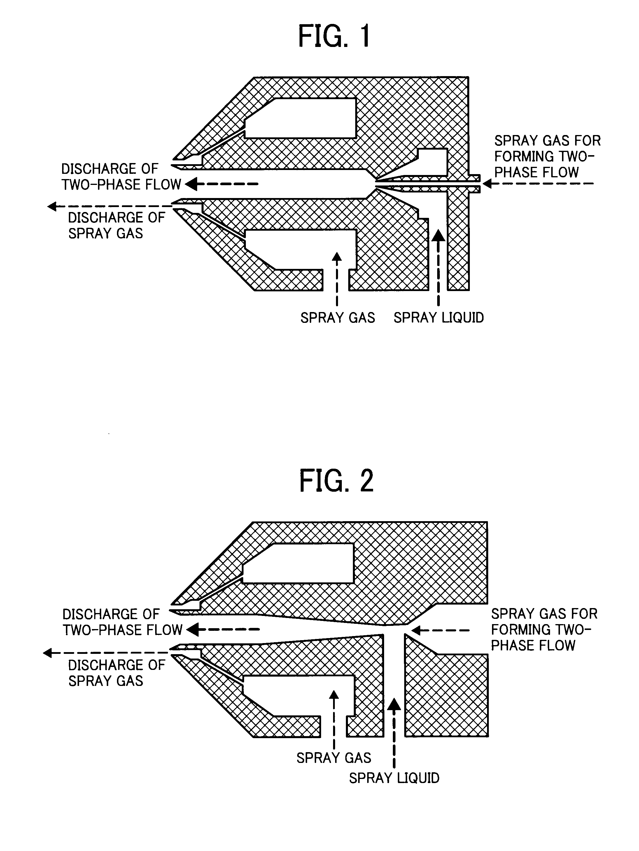
[0111]In Example 2, a spray nozzle having venturi structure was used. The spray nozzle was prepared by modifying the liquid passage of the spray nozzle AM45S so as to have a venturi structure. The venturi spray nozzle used has a structure as illustrated in FIG. 2. The other operation conditions were the same as those in Comparative Example 2.

example 3

5. Operation Conditions in Example 3

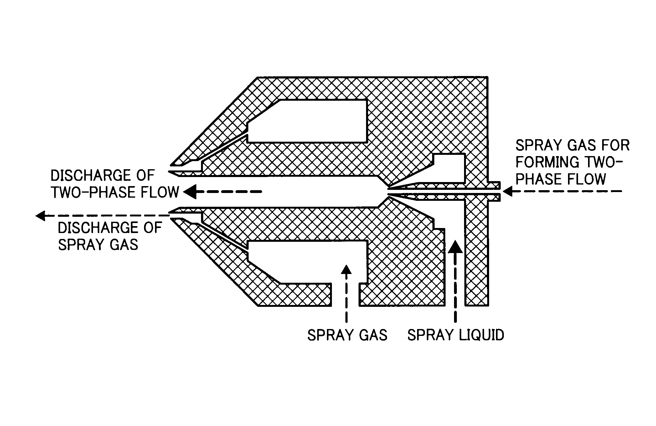
[0112]In Example 2, a spray nozzle having ejector structure was used. The spray nozzle was prepared by modifying the liquid passage of the spray nozzle AM45S so as to have an ejector structure. The ejector spray nozzle used has a structure as illustrated in FIG. 1. The other operation conditions were the same as those in Comparative Example 2.

[0113]The operation conditions are shown in Table 1.

TABLE 1PercentagePercentageMethodof primaryof sprayFormationforspray gasgas forofformingforformingMixingtwo-phasetwo-phaseformingtwo-phasemethodflowflowmistflowComp.InternalNo—  1 (100%) 0 (0%)Ex. 1mixingComp.ExternalNo—  1 (100%) 0 (0%)Ex. 2mixingEx. 1Two-phaseYesSimple0.9 (90%)0.1 (10%)flow,mixingExternalmixingEx. 2Two-phaseYesVenturi0.9 (90%)0.1 (10%)flow,ExternalmixingEx. 3Two-phaseYesEjector0.9 (90%)0.1 (10%)flow,Externalmixing

[0114]The results (i.e., the number of normally prepared batches of coated powder until a problem occurred) are shown in Table 2...


PUM


Abstract

A method for coating particles with a coating liquid including supplying airflow to fluidize the particles; mixing the coating liquid with a spray gas in a two-fluid spray nozzle to form a two-phase flow; and atomizing the two-phase flow with the spray gas to spray a mist of the coating liquid upon the particles. A coating device including a vessel; a fluidizing device configured to supply airflow to fluidize a powder in the vessel; and a spray nozzle configured to mix the coating liquid with a spray gas to form a two-phase flow, and to atomize the two-phase flow with the spray gas to spray a mist of the coating liquid. A particulate carrier for use in electrophotographic developer including particles of a core material and a cover layer thereon and prepared by the coating method mentioned above.

Description

BACKGROUND OF THE INVENTION[0001]1. Field of the Invention[0002]The present invention relates to a granulating / coating method for coating particles with a coating liquid. In addition, the present invention also relates to a granulating / coating device for coating particles with a coating liquid, and to a particulate carrier for use in a developer, which is used for image forming methods such as electrophotography, electrostatic recording, and electrostatic printing.[0003]2. Discussion of the Background[0004]Conventional granulating / coating devices typically perform one or more of the following processes:[0005](1) A process of spraying various raw materials into a vessel to prepare a particulate material constituted of the raw materials;[0006](2) A process of coating particles (hereinafter sometimes referred to as a powder), which is contained in a vessel, with a coating liquid; and[0007](3) A process of adhering the coated particles prepared in (2) to prepare aggregates of the partic...

Claims


Application Information

Patent Timeline
Patent Type & Authority Applications(United States)
IPC IPC(8): B05D7/00B05B7/24G03G13/06
CPCB01J2/16B05B7/0416B05B7/0433B05B7/066B05B7/10G03G9/107G03G9/1131G03G9/1136B29B9/12B29B9/10B29B2009/125
Inventor KINOSHITA, NAOTOSHITANAKA, TETSUYAKAWAMOTO, MASAHIROINA, HIROYUKIHITOSUGI, JUN
Owner RICOH KK
Why Eureka
Try Eureka