Low profile transverse connector

a transverse connector, low-profile technology, applied in the field of transverse connector systems, can solve the problems of inability to adjust the elevation of one end of the shluzas connector relative to the other end of the connector, the conventional effort to meet this need has fallen short of the desired transverse connector configuration, and the shluzas connector pivoting movement is limited. to achieve the effect of facilitating a secure connection

Active Publication Date: 2008-12-11
K2M
View PDF10 Cites 57 Cited by
  • Summary
  • Abstract
  • Description
  • Claims
  • Application Information

AI Technical Summary

Benefits of technology

[0009]The transverse connector system and method of application of the present invention provides a novel transverse connector having a first and second spinal rod connection member at opposing ends of an elongated cross connector device, each connection member having a distal end configured to be capable of connecting to a spinal rod and a proximal end having a multidirectional articulation joint at which a centrally disposed cross connecting assembly is provided to attach the first and second connection members to each other, the first and second spinal rod connection members each defining two opposing compression slots that serve to facilitate a secure connection to spinal rods and to the cross connecting assembly by the tightening of only one locking screw.

Problems solved by technology

Conventional efforts to meet this need have fallen short of the desired transverse connector configuration.
Importantly, the pivoting movement of the Shluzas connector is limited to movement within the same horizontal plane relative to the longitudinal axis of the spinal column.
That is, the elevation of one end of the Shluzas connector relative to the other end of the connector cannot be adjusted.
Thus, while the Shulzas design does provide some flexibility in adapting the alignment of the transverse connector to the opposing spinal rods, it falls short of the greater degree of adaptability that could be obtained by a truly multi-planar transverse connector having multiple articulating points.

Method used


Image

  • Low profile transverse connector
  • Low profile transverse connector
  • Low profile transverse connector

Examples


Embodiment Construction

[0029]Detailed embodiments of the present invention are disclosed herein; however, it is understood that the following description and each of the accompanying figures are provided as being exemplary of the invention, which may be embodied in various forms without departing from the scope of the claimed invention. Thus, the specific structural and functional details provided in the following description are non-limiting, but serve merely as a basis for the invention as defined by the claims provided herewith. The device described below can be modified as needed to conform to further development and improvement of materials without departing from the inventor's concept of the invention as claimed.

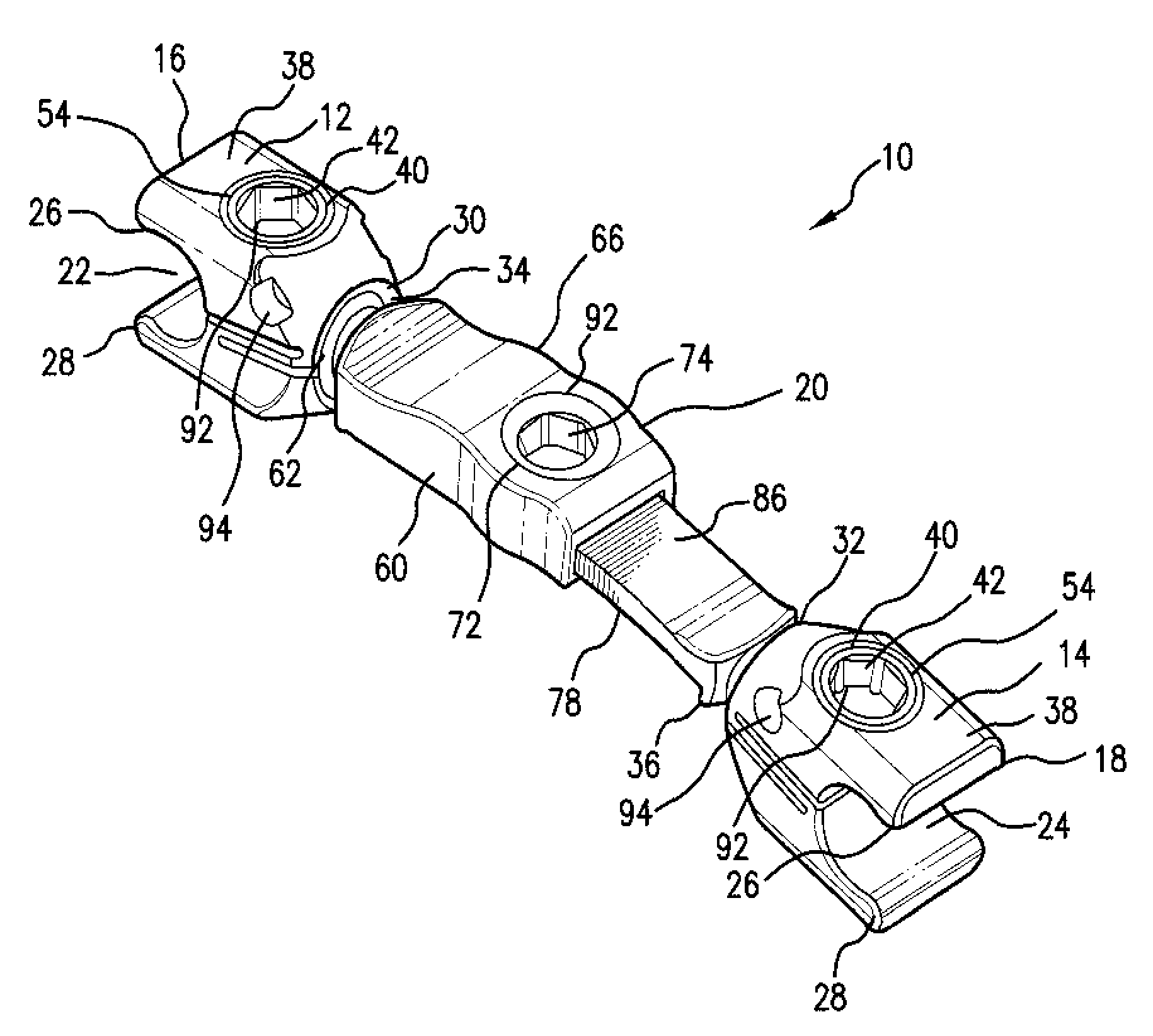
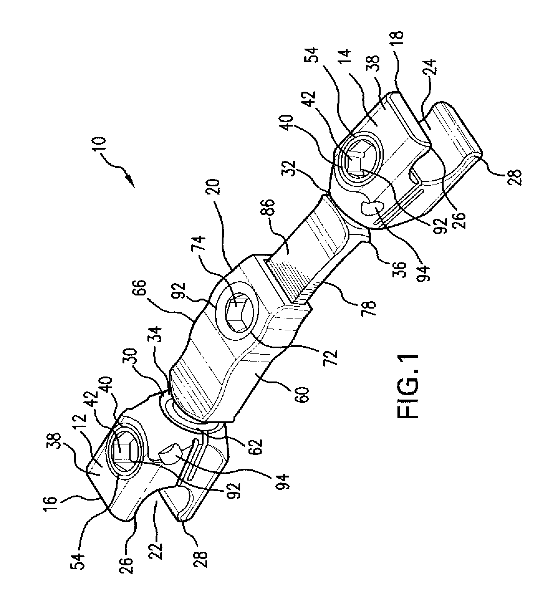
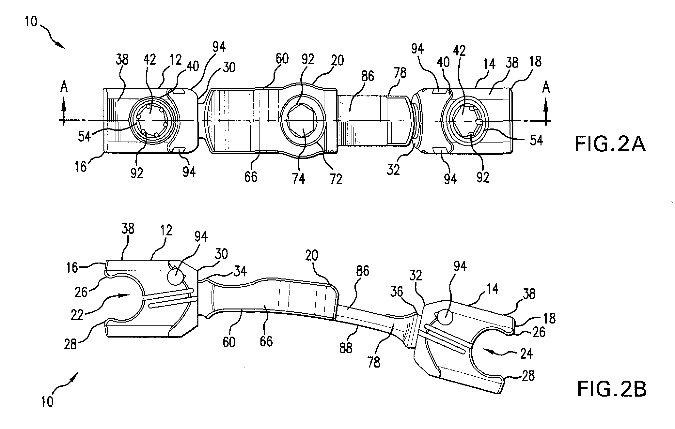
[0030]The low profile transverse connector system provides an elongated device, generally shown at 10 in FIGS. 1, 2A-B, 3, 4, 11A-C and 12, which includes a first and a second spinal rod connection member 12, 14, which are disposed at opposing first and second ends 16, 18 of the device 10, t...


PUM


Abstract

Provided is a novel low profile transverse connector system having a first and second spinal rod connection member disposed at opposing ends of an elongated cross connection device, each connection member having a distal end configured to be capable of connecting to a spinal rod and a proximal end having a multidirectional articulation joint at which a centrally disposed cross connecting assembly is provided to attach the first and second connection members to each other, the first and second spinal rod connection members each defining two opposing compression slots that serve to facilitate a secure connection to spinal rods and to the cross connecting assembly by the tightening of only one locking screw. Also provided is a method of stabilizing vertebrae using the disclosed system.

Description

BACKGROUND OF THE INVENTION[0001]1. Technical Field[0002]The present invention relates to a novel transverse connector system for interconnecting a first and a second rod, which are in an approximately parallel relationship to each other. More particularly the present invention relates to a novel low profile transverse connector system having opposing ends, which are configured to be capable of being securely attached to a first rod or second rod with each end of the connector system being capable of independent multidirectional articulation. The present invention also relates to a multidirectional articulating transverse connector system, the length of which can be easily increased or decreased and locked or unlocked in the selected configuration as needed.[0003]2. Background Art[0004]Disease, the effects of aging, or physical trauma resulting in damage to the spine has been treated in many instances by fixation or stabilization of the effected vertebra. A wide variety of spinal fi...

Claims


Application Information

Patent Timeline
Patent Type & Authority Applications(United States)
IPC IPC(8): A61B17/70A61B17/56
CPCA61B17/7052
Inventor MOORE, BRANDONJONES, SCOTT
Owner K2M
Why Eureka
Try Eureka