

Acetabular shell
a technology of acetabular and acetabular splint, which is applied in the field of orthopedics, can solve the problems of difficult incision and manipulation at the implantation site, devices including multiple extensions for connection with the pelvis, and often necessary, and achieve the effects of reducing cross-section, facilitating deformation, and reducing cross-section
- Summary
- Abstract
- Description
- Claims
- Application Information
AI Technical Summary
Benefits of technology
Problems solved by technology
Method used
Image

Examples
Embodiment Construction
[0031]As used herein, when referring to bones or other parts of the body, the term “proximal” means closer to the heart and the term “distal” means more distant from the heart. The term “inferior” means lower or bottom and the term “superior” means upper or top. The term “anterior” means towards the front part of the body or the face and the term “posterior” means towards the back of the body. The term “medial” means toward the midline of the body and the term “lateral” means away from the midline of the body.
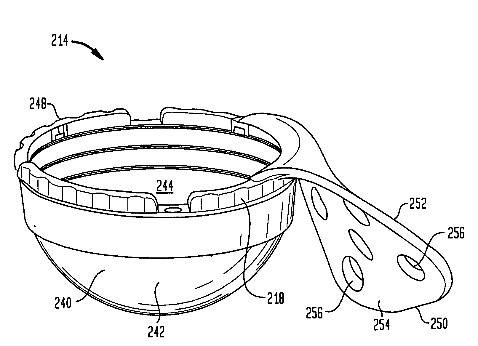
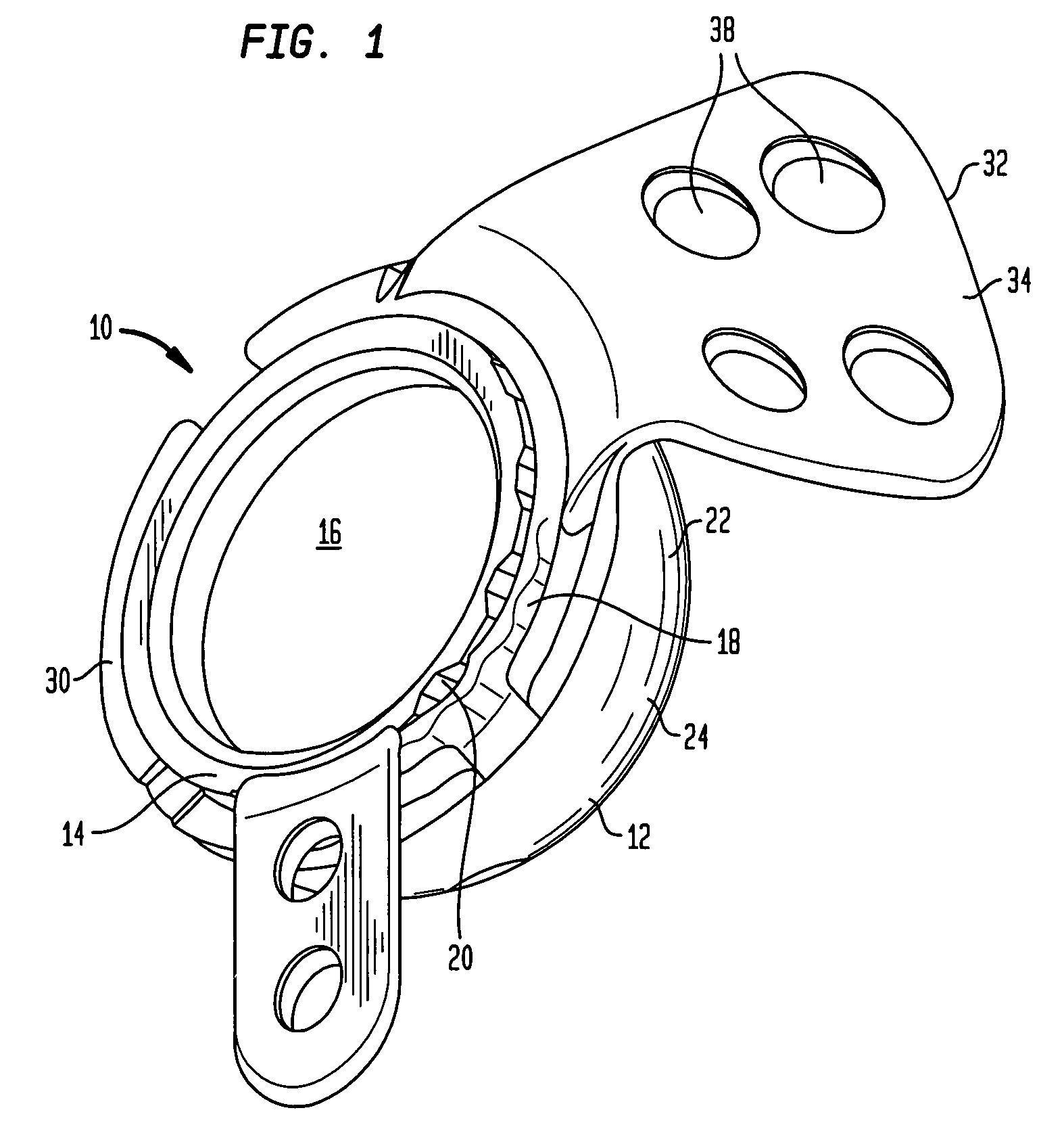
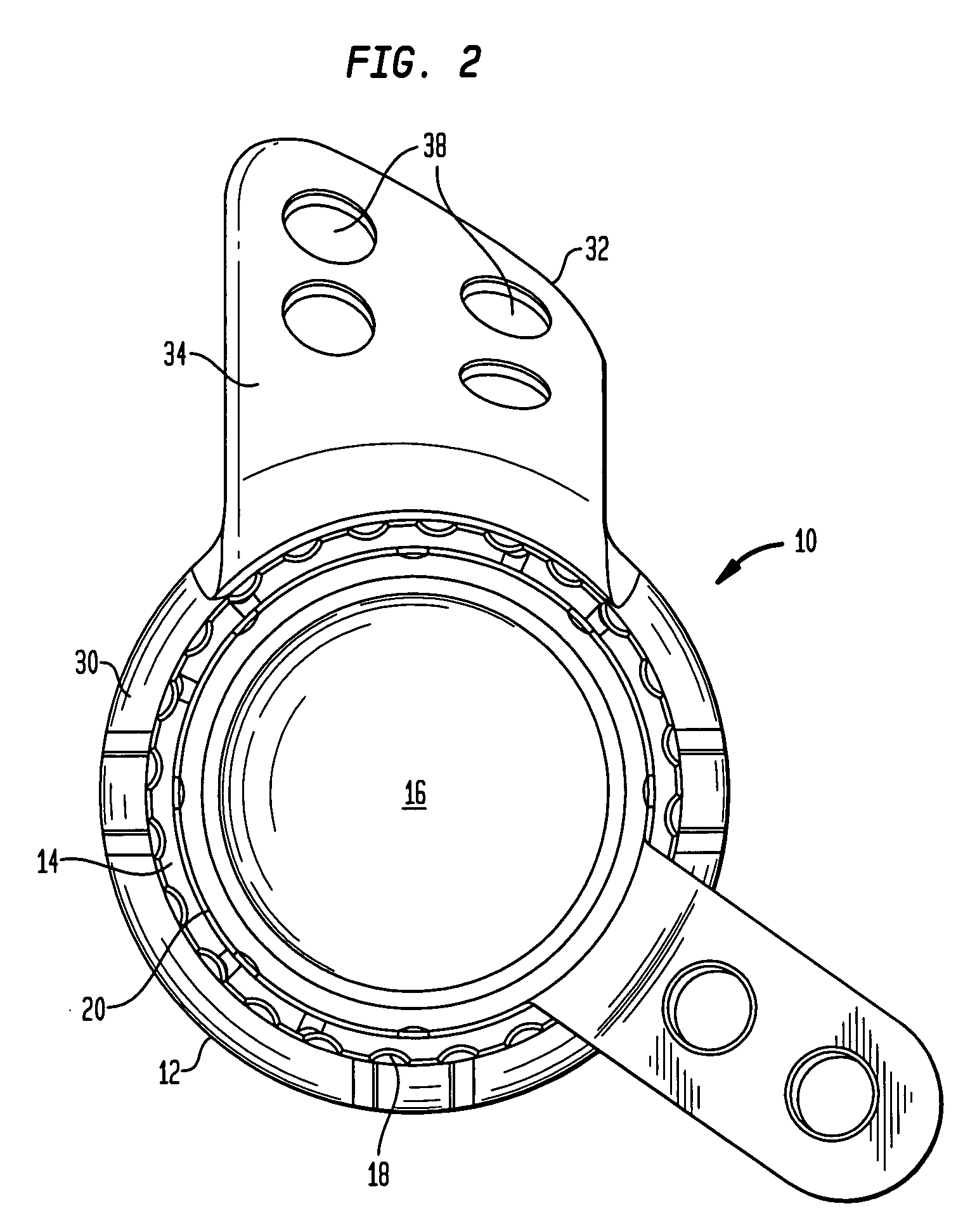
[0032]Referring to the drawings, wherein like reference numerals refer to like elements, there is shown in FIGS. 1-3, an acetabular cup replacement assembly designated generally by reference numeral 10. As shown in those figures, assembly 10 includes an outer shell portion 12, an adaptor portion 14, and an insert portion 16. Adaptor 14 is preferably designed both to be received within outer shell 12 and to receive insert 16. However, it is noted that shell 12 may also be capabl...
PUM
 Abstract
Description
Claims
Application Information