

Adaptive 3D Scanning
a 3d scanning and adaptive technology, applied in the field of adaptive 3d scanning, can solve the problems of inability to guarantee full coverage, long and time-consuming scan sequences, undesirable or unacceptable holes in scans,
Active Publication Date: 2008-12-11
3SHAPE AS
View PDF4 Cites 49 Cited by
- Summary
- Abstract
- Description
- Claims
- Application Information
AI Technical Summary
Problems solved by technology
An inherited problem with structured light 3D scanning is that both camera and light pattern need to “see” each surface point at the same time to be able to make a 3D reconstruction of that particular point.
Holes in the scan are in most cases undesirable or unacceptable both from a visual and application point of view.
However long and time consuming scan sequences is required to cover just simple shapes or objects with moderate shape variation.
In the case of objects with varying shapes this does still not guarantee full coverage.
Another problem is that the creation of the scan sequences can be very cumbersome and requires expert knowledge.
Artificial hole closing might give visually pleasant results, but the accuracy is very low, which is unacceptable for most application.
Method used
View moreImage
Smart ImageViewing Examples

Examples
fourth embodiment
[0067]In a fourth embodiment the invention relates to a computer software product containing sequences of instructions which when executed cause the method of the invention to be performed.
fifth embodiment
[0068]In a fifth embodiment the invention relates to an integrated circuit product containing sequences of instructions which when executed cause the method of the invention to be performed.
Login to View More PUM
 Abstract
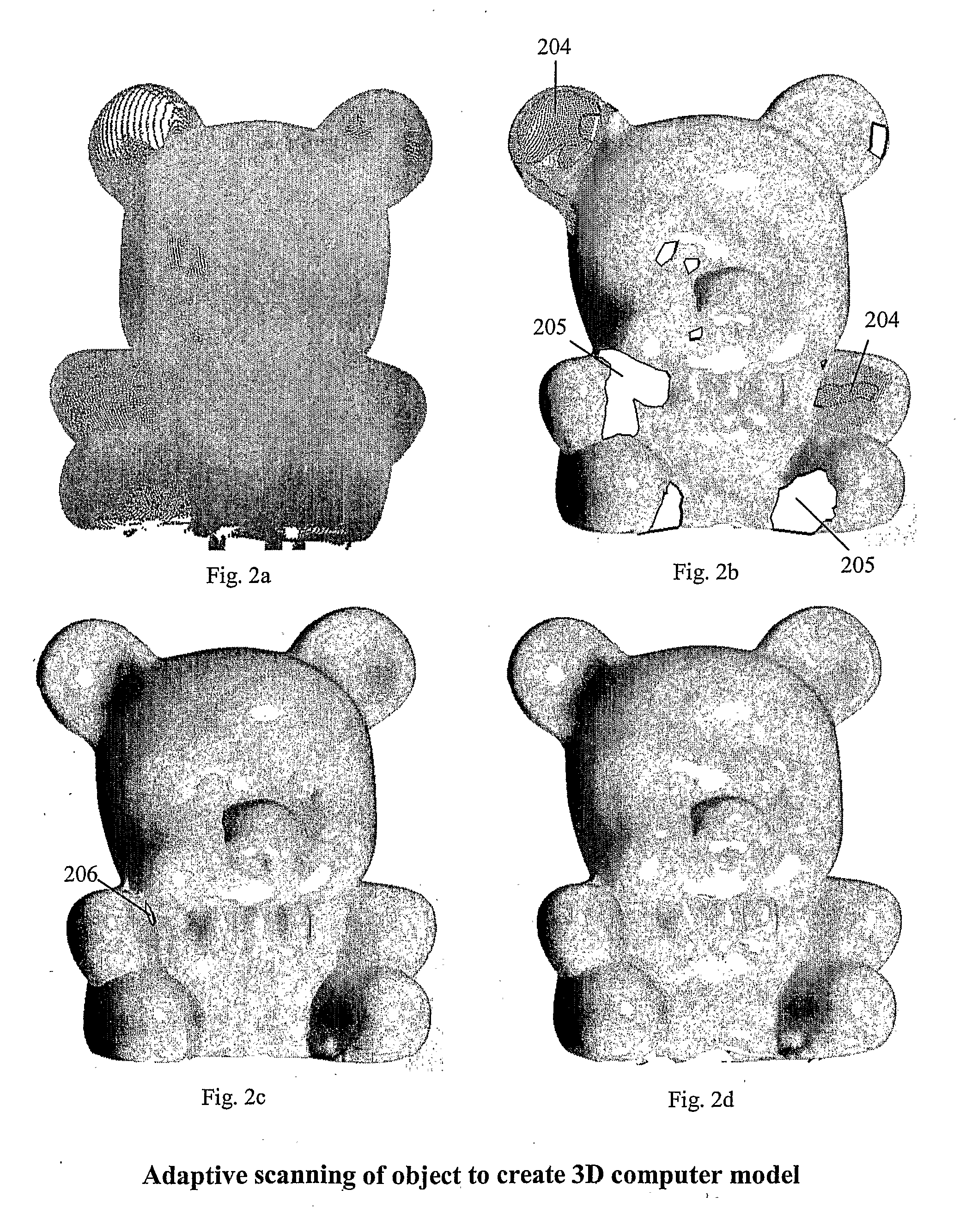
The present invention relates to adaptive 3D scanning wherein a scan sequence for obtaining full geometrical coverage of a physical object are created automatically and specifically for the physical object, by using a method and a system for producing a 3D computer model of a physical object, wherein the method comprises the following steps providing a scanner system, said scanner system comprising a scanner, and a computer connectable to and / or integrated in said scanner, said computer comprising a virtual model of said scanner, entering shape information of the physical object into the computer, creating in said computer a visibility function based on said virtual model and the shape information, said visibility function being capable of evaluating the coverage of areas of interest of the physical object by at least one predetermined scan sequence, establishing at least one scan sequence based on the evaluation of the visibility function, performing a scan of the physical object using said at least one scan sequence, and obtaining a 3D computer model of the physical object.
Description
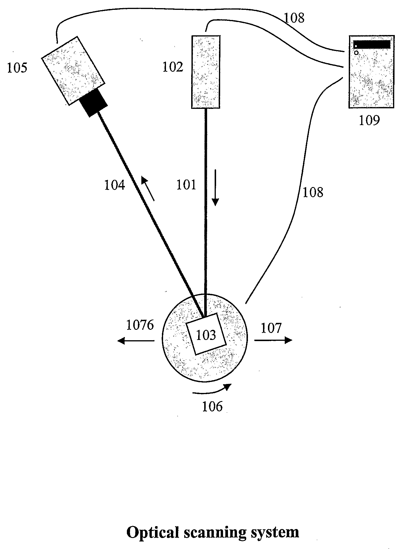
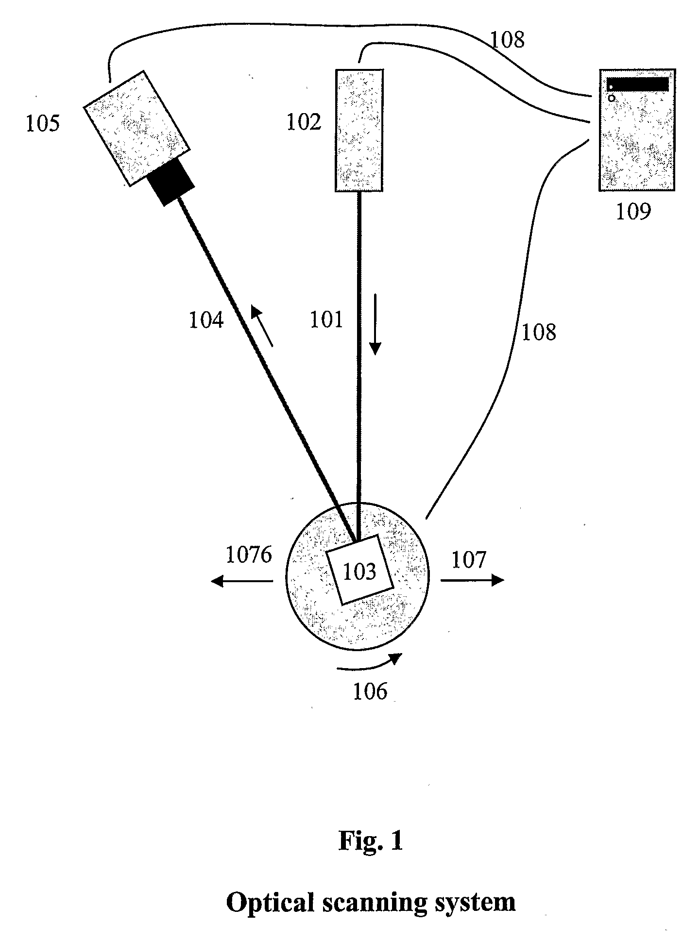
[0001]The present invention relates to production of 3D computer models of a physical object.BACKGROUND[0002]Structured light 3D scanner systems basically functioning the same way have been described in the prior art. They basically function as described in FIG. 1, wherein a monochromatic or multi spectral light pattern 101, such as laser dots, laser lines, white or colored strips, is projected from a light source 102 onto the object 103. The projected light is then reflected 104 and one or more cameras 105 acquire(s) images of the projection. The light pattern is detected in the image and well established projection geometry such as triangulation or stereo is used to derive the 3D coordinates, e.g. a line laser is projected onto the object forming a line. The 3D coordinates are then reconstructed along that particular line. The scanner may contain one or more light sources / patterns and one or more cameras.[0003]The next step is then to move the object and scanner relative to each o...
Claims
Login to View More Application Information
Patent Timeline
 Patent Type & AuthorityApplications(United States)
IPC IPC(8): G01B11/24
CPCY10S359/90G06T17/00
InventorFISKER, RUNECLAUSEN, TAISDEICHMANN, NIKOLAJOJELUND, HENRIK
Owner3SHAPE AS