
Canonical model to normalize disparate persistent data sources

a persistent data source and canonical model technology, applied in the field of methods to normalize and monitor disparate persistent data sources, can solve the problems of difficult monitoring and evaluation of the category “employees”, difficult to match this information efficiently, and difficult to integrate data from different applications

Inactive Publication Date: 2008-12-11
INT BUSINESS MASCH CORP
View PDF9 Cites 14 Cited by
  • Summary
  • Abstract
  • Description
  • Claims
  • Application Information

AI Technical Summary

Benefits of technology

Enables virtually real-time monitoring across multiple databases without straining resources, providing normalized data for reporting and alerting, and allowing for seamless updates by changing ontologies at runtime rather than recoding.

Problems solved by technology

Most organizations have information management problems that require access to timely information for business monitoring, including the need to integrate many disparate applications in order to provide that information completely.
Many of these applications come from different vendors who use their own nomenclature for application metadata, which makes the integration of data from the different applications very difficult.
One database may use the term “customer_number,” but another database may refer to the same data as “customer_no” and a third database as “customer_id,” making it hard to match this information efficiently.
For example, one database may define the term “employee” to include full-time employees as well as part-time employees and contractors, but another database may exclude contractors from the category “employee.” This can make it very difficult to monitor and evaluate the category “employee,” over multiple databases.
The disadvantage of this approach for alerting and notification purposes is that not all application functions result in a message being generated to another system.
However, one disadvantage of this process is that special programs must be written for the conversion of data from the different databases, which is time-consuming and expensive.
Moreover, the traffic load of this process strains the resources of the databases when the data is being pulled from them.
The ETL process, even though run at night, will create a significant degradation in transaction response times for end users of the databases.
This is a major disadvantage since, with the advent of the Internet, databases typically must function at a high level twenty-four hours a day, every day.
In addition, once this process has been put into place it can be disrupted or broken if one or more of the databases involved are updated.
Another problem with this approach is that the data it provides is not available in real time, although real-time monitoring of databases can be crucial for a business.

Method used


Image

  • Canonical model to normalize disparate persistent data sources
  • Canonical model to normalize disparate persistent data sources
  • Canonical model to normalize disparate persistent data sources

Examples


example 1

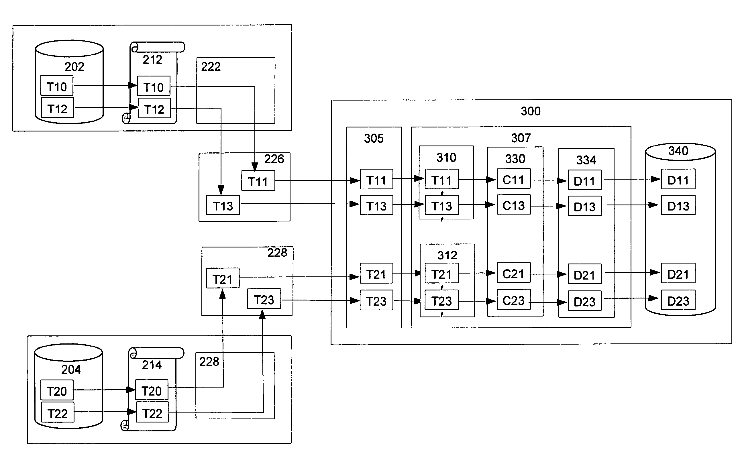
[0061]FIG. 6 illustrates an example of transactions T10 and T12 from database 202 and transactions T20 and T22 from database 204. Transaction T10 is logged on data log 212 and replicated by replication agent 222 to transaction T11 in a first event stream 226. Transaction T12 is logged on data log 212 and replicated to transaction T13 in the first event stream 226. Data reader 305 captures the first event stream 226, and directs transactions T11 and T13 to the inference engine 307 where the transactions are transformed to transactions T11′ and T13′ according to a first source ontology 310 and then normalized to canonical form by canonical ontology 330 and stored as canonical instances C11 and C13 respectively in the canonical database 340.

[0062]Similarly, transaction T20 is logged on data log 214 and replicated by replication agent 224 to transaction T21 in a second event stream 228. Transaction T22 is logged on data log 214 and replicated to transaction T23 in the second event strea...

example 2

Using a Destination Ontology

[0064]To show the use of a destination ontology 334, FIG. 7 illustrates the example given above of transactions T10 and T12 from database 202 and transactions T20 and T22 from database 204. Transaction T10 is logged on data log 212 and replicated by replication agent 222 to transaction T11 in a first event stream 226. Transaction T12 is logged on data log 212 and replicated to transaction T13 in the first event stream 226. Data reader 305 captures the first event stream 226 and directs transactions T11 and T13 to the inference engine 307, where the transactions are transformed to transactions T11′ and T13′ according to a first source ontology 310 and then normalized to canonical form C11 and C13 respectively by canonical ontology 330. C11 and C13 are then transformed into a target database's metadata language as D11 and D13 respectively by destination ontology 334, and D11 and D13 are stored in the canonical database 340.

[0065]Similarly, transaction T20 i...


PUM


Abstract

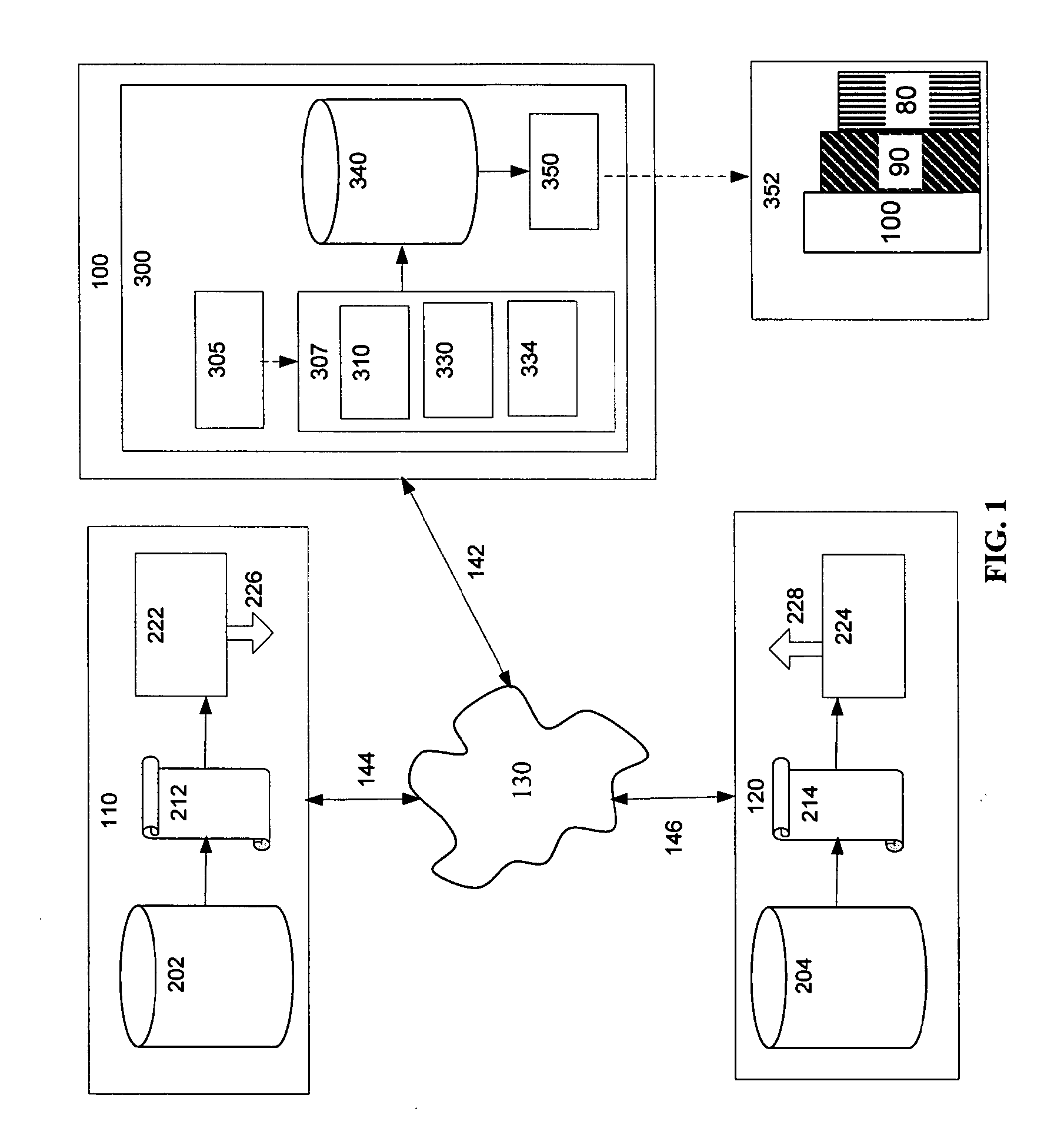
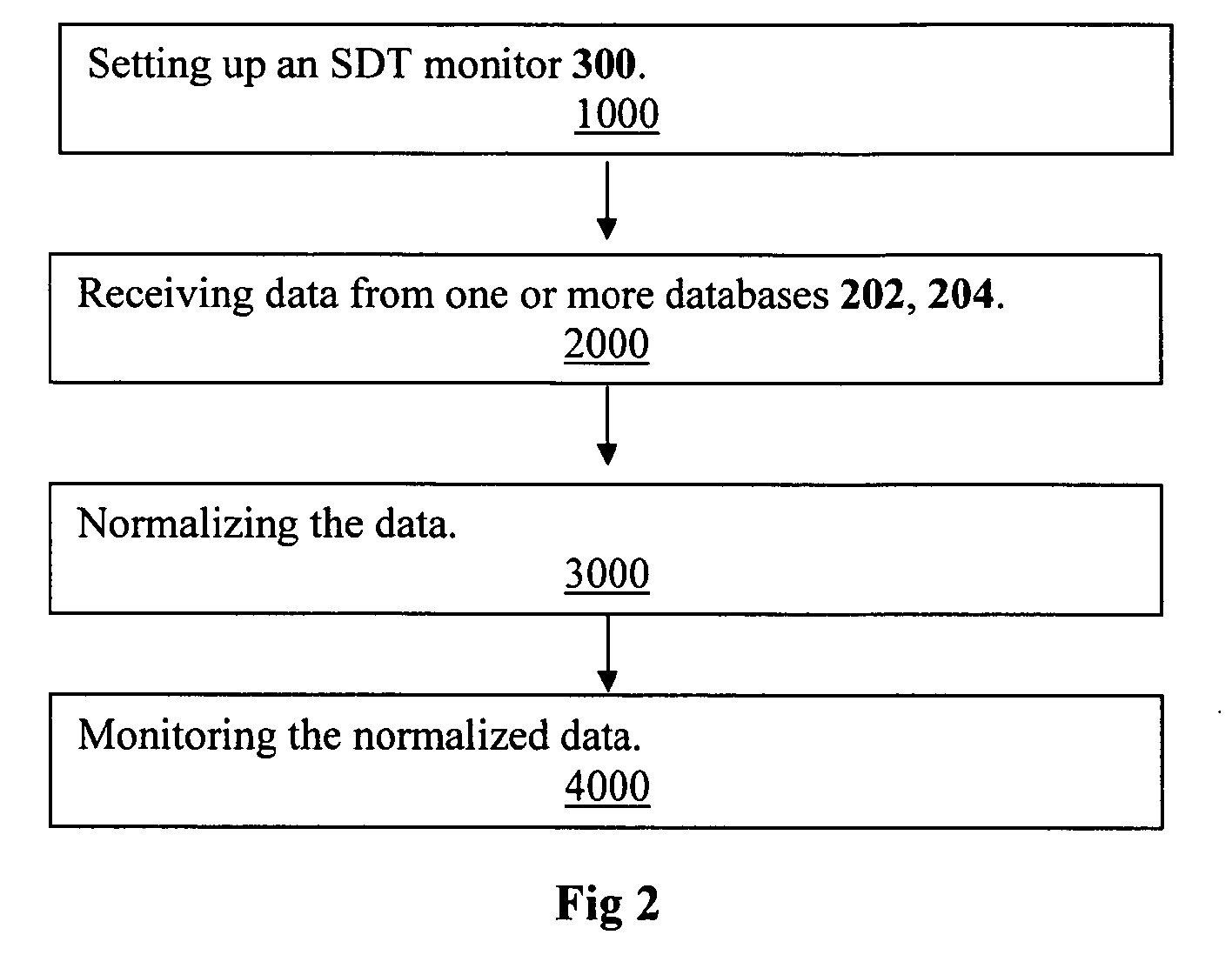
A semantic database transaction monitor is provided that monitors database transactions by taking advantage of database replication technology. The invention receives one or more event streams of transaction data from one or more database replication software agents, originally from transaction logs, and then classifies each transaction, utilizing an inference engine populated with one or more source ontologies and a canonical ontology so that transaction metadata are normalized. The invention then can be utilized to create a data store across multiple databases for reporting and analysis. The invention can also be used to feed normalized database transactions to real-time graphics software for real-time reporting or alerting. Because the process obtains data from event streams, it does not significantly drain the resources of the databases and can provide virtually real-time monitoring. Moreover, it does not require recoding for updates to the databases, but only changes to the ontologies read at runtime.

Description

CROSS-REFERENCE TO RELATED APPLICATIONS[0001]This application claims the benefit of PPA Ser. No. 60 / 715,108, filed Sep. 8, 2005 by the present inventor.FIELD OF THE INVENTION[0002]This innovation relates to a method to normalize and monitor disparate persistent data sources.BACKGROUND OF THE INVENTION[0003]Most organizations have information management problems that require access to timely information for business monitoring, including the need to integrate many disparate applications in order to provide that information completely. Many of these applications come from different vendors who use their own nomenclature for application metadata, which makes the integration of data from the different applications very difficult.[0004]For example, an insurance company may use different databases, with different applications purchased from different vendors, to provide underwriting, rate quotes, and motor vehicle information, each of which may have its own lexical and semantic convention...

Claims


Application Information

Patent Timeline
Patent Type & Authority Applications(United States)
IPC IPC(8): G06F17/30
CPCG06F17/30563G06F16/254
Inventor GILMAN, JOHN
Owner INT BUSINESS MASCH CORP
Learn More