Brush section for an electric toothbrush

a brush head and electric toothbrush technology, applied in the field of electric toothbrushes, can solve the problems of reducing the effectiveness of the brush head design and cleaning action, difficulty in changing habits, and reducing the effectiveness of the electric toothbrush, so as to enhance the cleaning action of the head section, enhance the cleaning action, and facilitate use.

Active Publication Date: 2008-12-18
THE PROCTER & GAMBLE COMPANY +1
View PDF12 Cites 80 Cited by
  • Summary
  • Abstract
  • Description
  • Claims
  • Application Information

AI Technical Summary

Benefits of technology

[0022]FIGS. 1-3 illustrate a brush section 10 which may be push-fitted onto a toothbrush handle section and coupled to the drive shaft of the handle section, such for example, as a handle section described above. The brush section includes a mounting tube 12 extending along an axis 14. The axis 14 is a longitudinal axis of the cleaning section and may coincide with a longitudinal section of the drive shaft 38 (FIG. 3). At a first end 16 (FIG. 1), the mounting tube 12 may include a profile ring 18 having an inside contour complementary with an outside contour of the handle section. In this manner, the brush section 10 can be push-fitted onto the handle section in a manner preventing relative rotation of the brush section with respect to the handle section. A tab / slot, key / spline or other similar structure may be included in the corresponding contour surfaces to facilitate alignment of the brush section with the handle section and to further prevent relative rotation between the two.
[0064]As described, the various arrangements of a bristle holder portion, e.g., 150, 150′ and 150, etc., permit relatively complex rotational and translational cleaning motions to be imparted to the second plurality of bristles 128. This may be accomplished with a simple rotating motion of the drive shaft 138 making brush sections 110 incorporating these configurations easily adaptable to existing handle section designs that may provide only for a rotating drive shaft output.

Problems solved by technology

For the electric toothbrush having a circular brush head design and employing a rotary or rotary-oscillating cleaning motion, using this electric toothbrush with a manual brushing action can be counter productive and may reduce the effectiveness of the brush head design and cleaning action.
Ironically, the electric toothbrush is rendered less effective while the consumer erroneously believes the added action makes for a more effective and / or expedited cleaning process.
Furthermore, years of training and conditioning have taught the consumer to use a circular or vertical cleaning motion, and habits may be difficult to change.

Method used


Image

  • Brush section for an electric toothbrush
  • Brush section for an electric toothbrush
  • Brush section for an electric toothbrush

Examples


Embodiment Construction

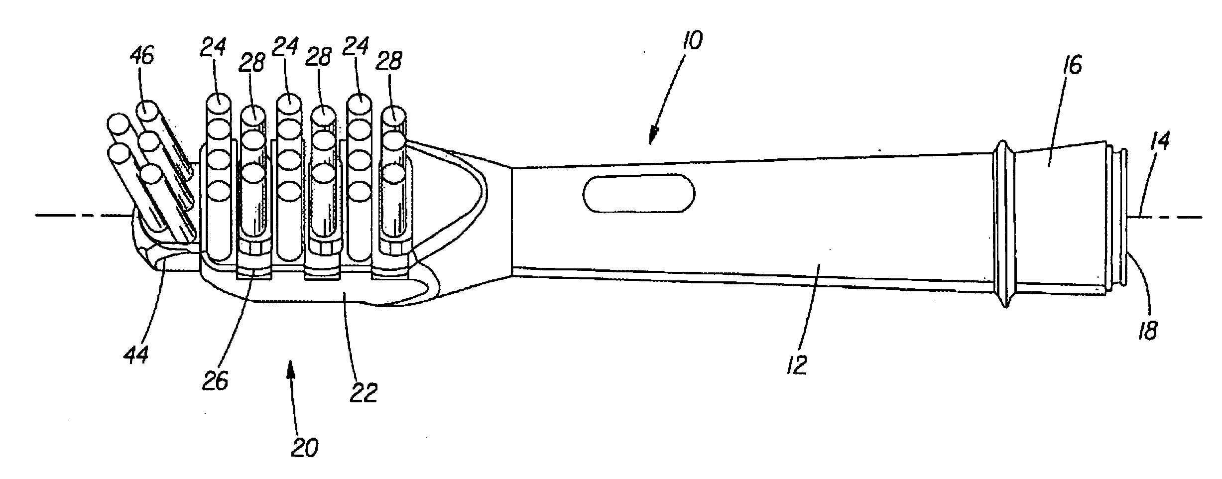
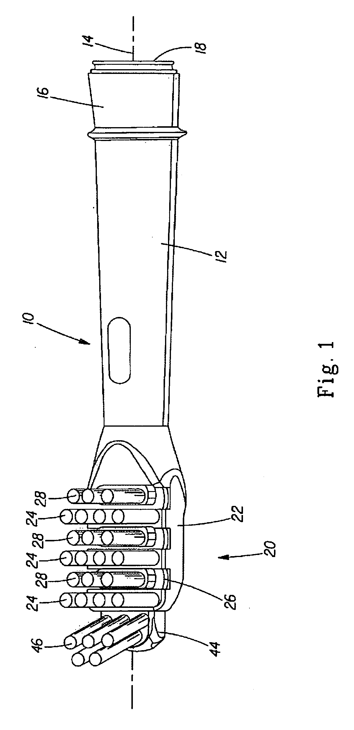
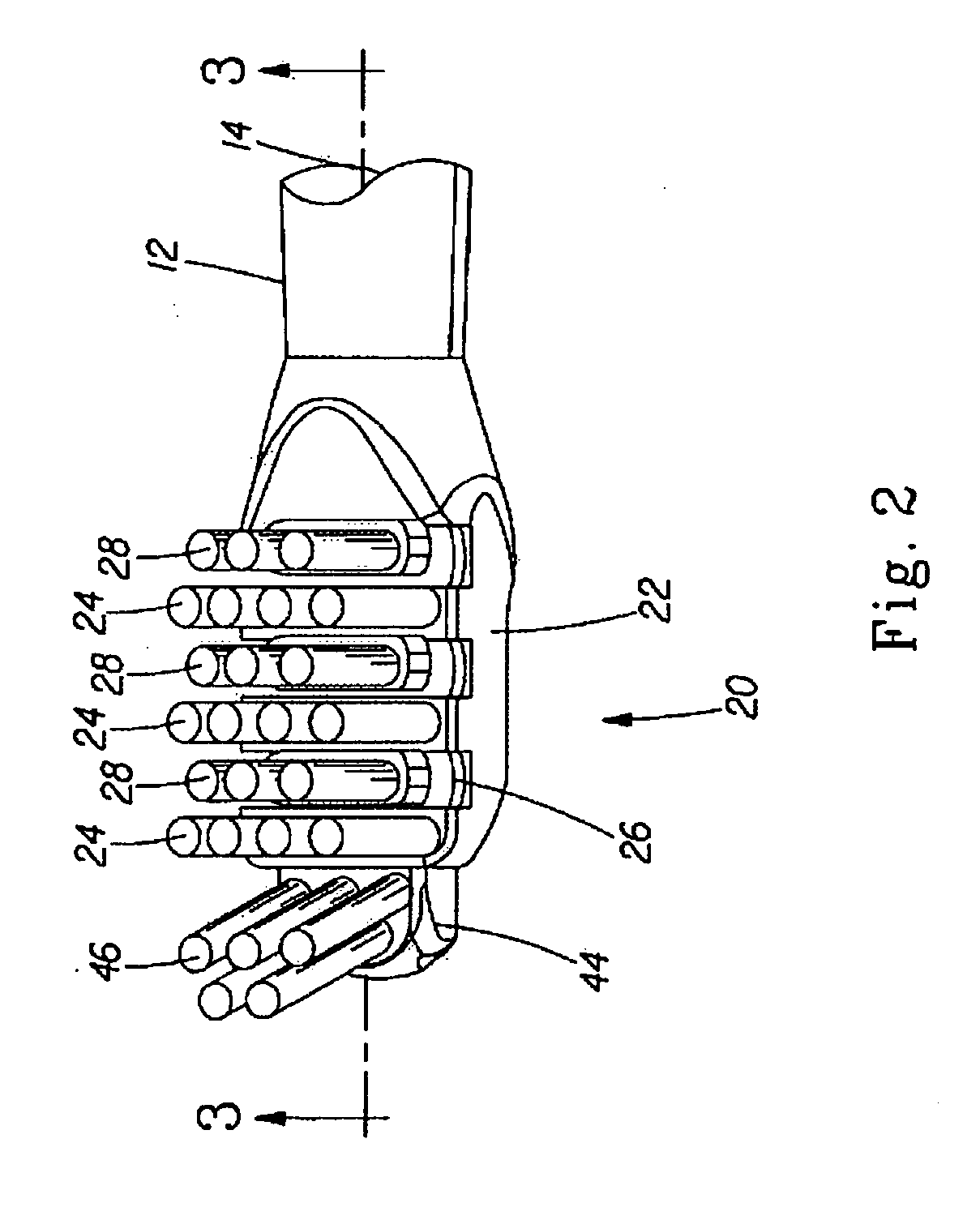
[0018]A brush section for use with an electric toothbrush includes a brush head portion which may have a generally rectangular shape, although oblong, elliptical, or any suitable shape may be employed. Generally, the brush head portion may have a length-to-width aspect ratio greater than 1, although such an arrangement is not required. The brush head portion is secured to a tube member of the brush section that may be configured to couple to a handle section. The handle section may include an electric drive including a drive shaft, and the drive shaft may couple to the brush head via a coupling or drive pin member positioned within the tube member. In some embodiments, the electric drive may impart a rotary, oscillating, rotary-oscillating or other suitable drive motion to the drive shaft that is, in turn, imparted upon the brush head and bristle members thereof by virtue of the coupling member.

[0019]The brush head may incorporate a first plurality of cleaning bristles that are stat...


PUM


Abstract

A brush section for use with an electric toothbrush includes a relatively large brush head portion having a generally rectangular shape, although oblong, elliptical and other such shapes having a length to width aspect ration greater than 1 may be employed. The brush head portion is secured to a shaft portion of the brush section that may be configured to couple to a handle section. The handle section may include an electric drive including drive shaft, and the drive shaft may couple to the brush head via a coupling member positioned within the shaft portion. The electric drive may impart a rotary, oscillating rotary-oscillating or other suitable drive motion to the drive shaft that is, in turn, imparted upon the brush head by virtue of the coupling member.

Description

FIELD OF THE INVENTION[0001]This application claims the benefit of U.S. Provisional Patent Application No. 60 / 899,280 filed on Feb. 2, 2007, which is incorporated here by reference. This patent relates to electric toothbrushes and in particular to a brush section for an electric toothbrush.BACKGROUND OF THE INVENTION[0002]An electric toothbrush may incorporate a brush section that couples to a handle section. A drive shaft may extend from the handle section with the drive shaft being coupled to an electric drive disposed within an interior of the handle section. The electric drive may impart a rotary, oscillating or combined rotary oscillating motion to the drive shaft so that the drive shaft is movable in a rotary or oscillating manner. The brush section can couple and secure to the handle section with the drive shaft coupling to a coupling element of the brush section, e.g., a shaft or drive pin. The motion of the drive shaft can be imparted upon the coupling element to provide a ...

Claims


Application Information

Patent Timeline
Patent Type & Authority Applications(United States)
IPC IPC(8): A46B13/00A46B9/04A46D1/00
CPCA61C17/3418A61C17/3454A61C17/16A46B9/04A61C17/349A46B7/00A46B13/00A61C17/3409
Inventor FARRELL, MARK EDWARDBLAIN, CHRISTOPHER CHARLESBRAUN, PHILLIP MAURICE
Owner THE PROCTER & GAMBLE COMPANY
Why Eureka
Try Eureka