[0007]In view of the foregoing problems, it is an object of the present invention to provide an air flow measuring device, which can improve detection accuracy of a flow amount sensor.
[0008]It is another object of the present invention to provide an air flow measuring device, which can
restrict a separation of an air flow from a tube body so as to improve detection accuracy of a flow amount sensor.
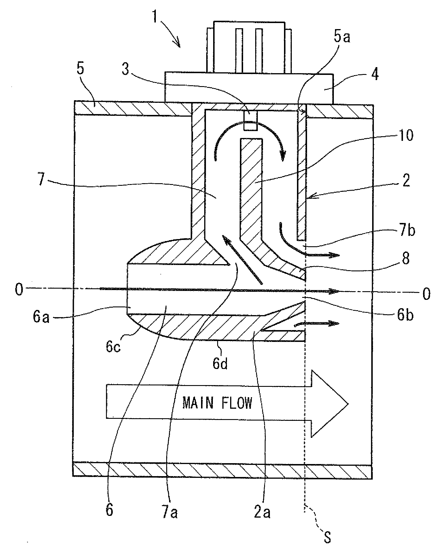
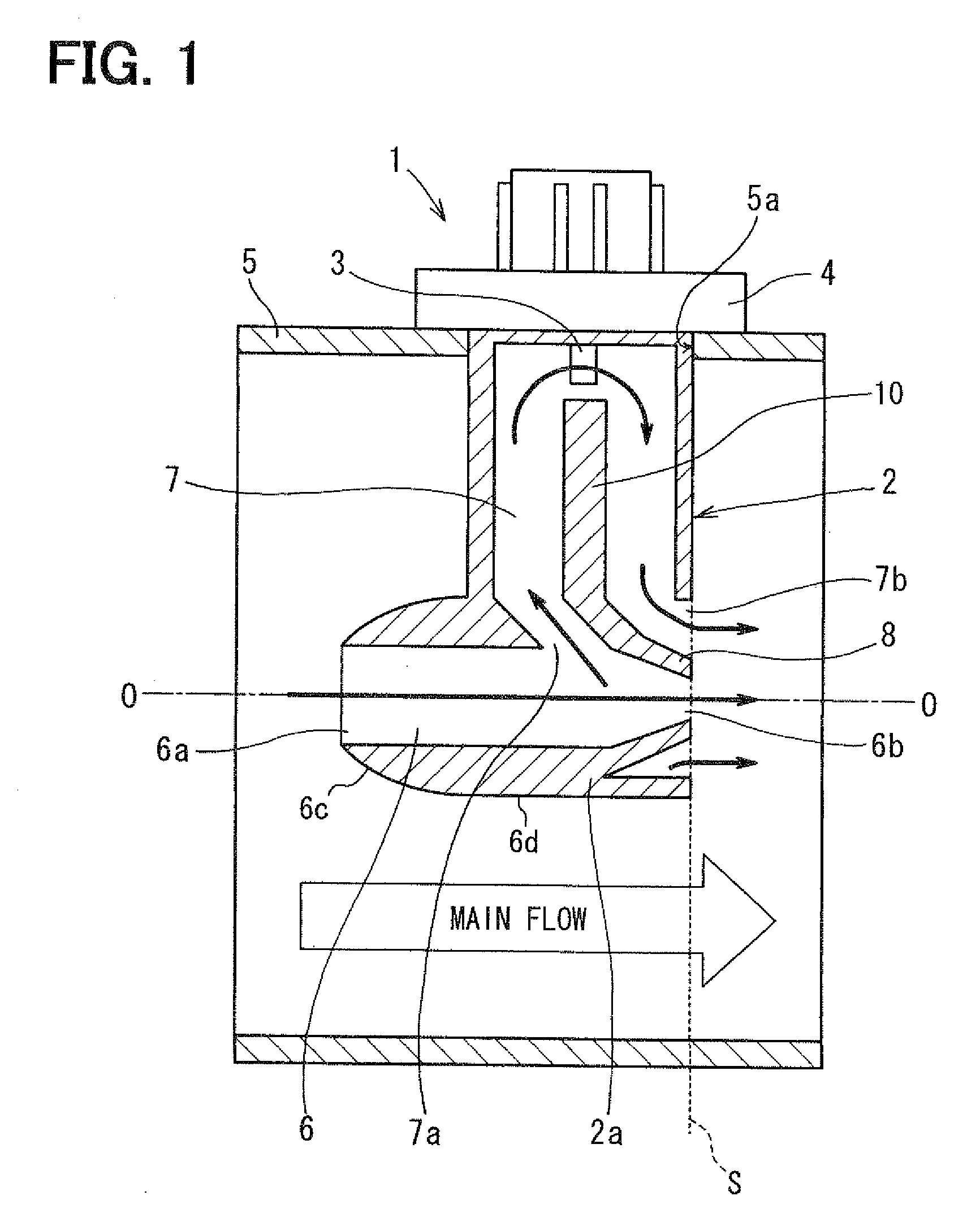
[0009]According to an aspect of the present invention, an air flow measuring device for measuring a flow amount of air flowing in an interior of a duct includes a tube body for defining a bypass passage configured to introduce therein a part of air flowing in the duct, a sub-bypass passage branched from the bypass passage and being configured to introduce therein a part of air flowing in the bypass passage, and a flow amount sensor located in the sub-bypass passage to measure a flow amount of air flowing in the sub-bypass passage. In the air flow measuring device, an upstream end surface of the tube body has an inlet of the bypass passage, open toward upstream in the duct, and a downstream end surface of the tube body has an outlet of the bypass passage, open toward downstream in the duct. The tube body has an outer peripheral surface extending from the upstream end surface to the downstream end surface, and an outer
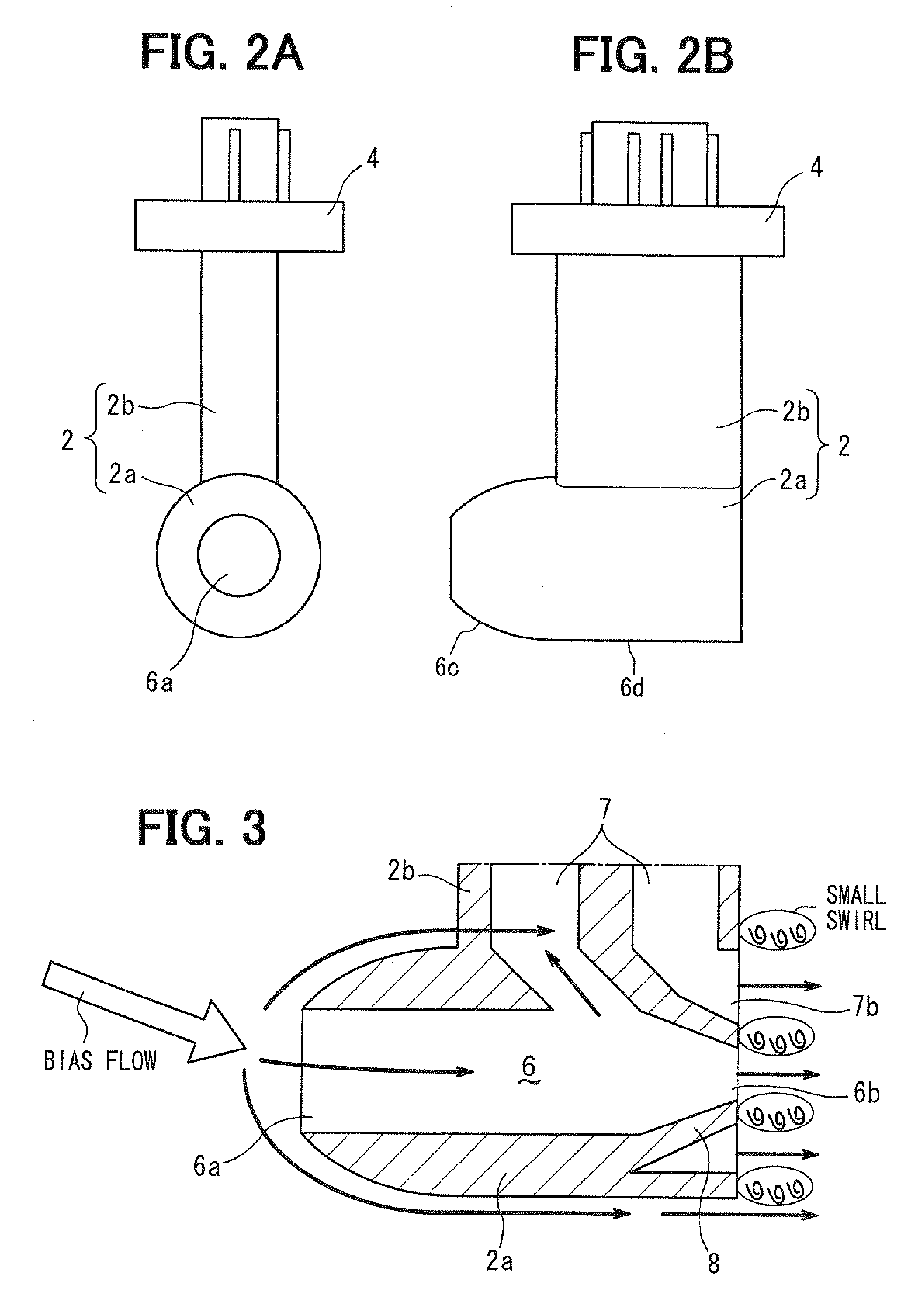
diameter of the outer peripheral surface of the tube body has a smallest dimension at the upstream end surface and a largest dimension at the downstream end surface. Furthermore, the outer peripheral surface of the tube body has a first portion extending downstream from the upstream end surface in a predetermined range, and the first portion of the outer peripheral surface is a convex curve surface in which the outer diameter is increased by a ratio from a position on the upstream end surface toward downstream. Because the first portion of the tube body is constructed of the convex curve surface, the
pressure resistance of air on the tube body can be made small, thereby restricting a large disturbance of air flowing along the outer peripheral surface of the tube body and restricting a separation of air flow from the tube body. As a result, a flow speed of air flowing in the bypass passage can be made stable without greatly changing a
pressure difference between the inlet and outlet of the bypass passage. Accordingly, in the air flow measuring device, detection accuracy of the flow amount sensor can be improved.
[0011]According to another aspect of the present invention, an air flow measuring device for measuring a flow amount of air flowing in an interior of a duct includes a tube body for defining a bypass passage configured to introduce therein a part of air flowing in the duct, a sub-bypass passage branched from the bypass passage and being configured to introduce therein a part of air flowing in the bypass passage, and a flow amount sensor located in the sub-bypass passage to measure a flow amount of air flowing in the sub-bypass passage. In the air flow measuring device, an upstream end surface of the tube body has an inlet of the bypass passage, open toward upstream in the duct, and a downstream end surface of the tube body has an outlet of the bypass passage, open toward downstream in the duct. The tube body has an outer peripheral surface extending from the upstream end surface to the downstream end surface. Furthermore, an outer diameter of the outer peripheral surface of the tube body has a smallest dimension at the upstream end surface and a largest dimension at the downstream end surface, and the outer peripheral surface of the tube body has a convex curve surface in which the outer diameter is increased by a ratio from a position on the upstream end surface to a position on the downstream end surface. Accordingly, the
pressure resistance of air on the tube body can be made small, thereby restricting a large disturbance of air flowing along the outer peripheral surface of the tube body and restricting a separation of air flow from the tube body. As a result, a flow speed of air flowing in the bypass passage can be made stable without greatly changing a
pressure difference between the inlet and outlet of the bypass passage. Therefore, in the air flow measuring device, detection accuracy of the flow amount sensor can be improved.
[0012]According to another aspect of the present invention, an air flow measuring device for measuring a flow amount of air flowing in an interior of a duct includes a tube body for defining a bypass passage configured to introduce therein a part of air flowing in the duct, and a flow amount sensor located in the bypass passage to measure a flow amount of air flowing in the bypass passage. In the air flow measuring device, an upstream end surface of the tube body has an inlet of the bypass passage, open toward upstream in the duct, and a downstream end surface of the tube body has an outlet of the bypass passage, open toward downstream in the duct. The tube body has an outer peripheral surface extending from the upstream end surface to the downstream end surface, and an outer diameter of the outer peripheral surface of the tube body has a smallest dimension at the upstream end surface and a largest dimension at the downstream end surface. In addition, the outer peripheral surface of the tube body has a first portion extending downstream from the upstream end surface in a predetermined range, and the first portion of the outer peripheral surface is a convex curve surface in which the outer diameter is increased by a ratio from a position on the upstream end surface, toward downstream. Accordingly, the
pressure resistance of air on the tube body can be made small, thereby restricting a large disturbance of air flowing along the outer peripheral surface of the tube body and restricting a separation of air flow from the tube body. As a result, a flow speed of air flowing in the bypass passage can be made stable without greatly changing a
pressure difference between the inlet and outlet of the bypass passage. Therefore, in the air flow measuring device, detection accuracy of the flow amount sensor can be improved.
[0014]According to further another aspect of the present invention, an air flow measuring device for measuring a flow amount of air flowing in an interior of a duct includes a tube body for defining a bypass passage configured to introduce therein a part of air flowing in the duct, and a flow amount sensor located in the bypass passage to measure a flow amount of air flowing in the bypass passage. In the air flow measuring device, an upstream end surface of the tube body has an inlet of the bypass passage, open toward upstream in the duct, and a downstream end surface of the tube body has an outlet of the bypass passage, open toward downstream in the duct. The tube body has an outer peripheral surface extending from the upstream end surface to the downstream end surface, and an outer diameter of the outer peripheral surface of the tube body has a smallest dimension at the upstream end surface, and a largest dimension at the downstream end surface. Furthermore, the outer peripheral surface of the tube body has a convex curve surface in which the outer diameter is increased by a ratio from the upstream end surface to the downstream end surface. Accordingly, in the air flow measuring device, detection accuracy of the flow amount sensor can be improved.

