Load sensor-equipped operating apparatus

Inactive Publication Date: 2008-12-18
TOYODA IRON WORKS CO LTD
View PDF8 Cites 14 Cited by
  • Summary
  • Abstract
  • Description
  • Claims
  • Application Information

AI Technical Summary

Benefits of technology

[0044]With this structure, the transmittal link is mechanically and reliably pivoted with the movable operation of the operational member, resulting in that the direction of relative displacement between the shaft-like member and the main body member of the load sensor is maintained substantially constant with high accuracy. In addition to this, even when the load is not applied, for example, upon non-operation of the operational member, the engagement between the positioning hole and the sensor pin maintains the constant orientation of the first member. Also, since the orientation of the transmittal link connected to

Problems solved by technology

As a result, firstly, the structure of the apparatus becomes complicated.
Consequently, this type of apparatus is large-size and becomes expensive as a whole.
Nevertheless,

Method used


Image

  • Load sensor-equipped operating apparatus
  • Load sensor-equipped operating apparatus
  • Load sensor-equipped operating apparatus

Examples


Example

[0079]In the following, embodiments of the present invention will be described with reference to the drawings.

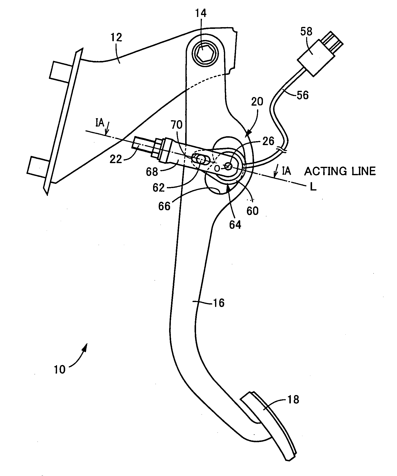
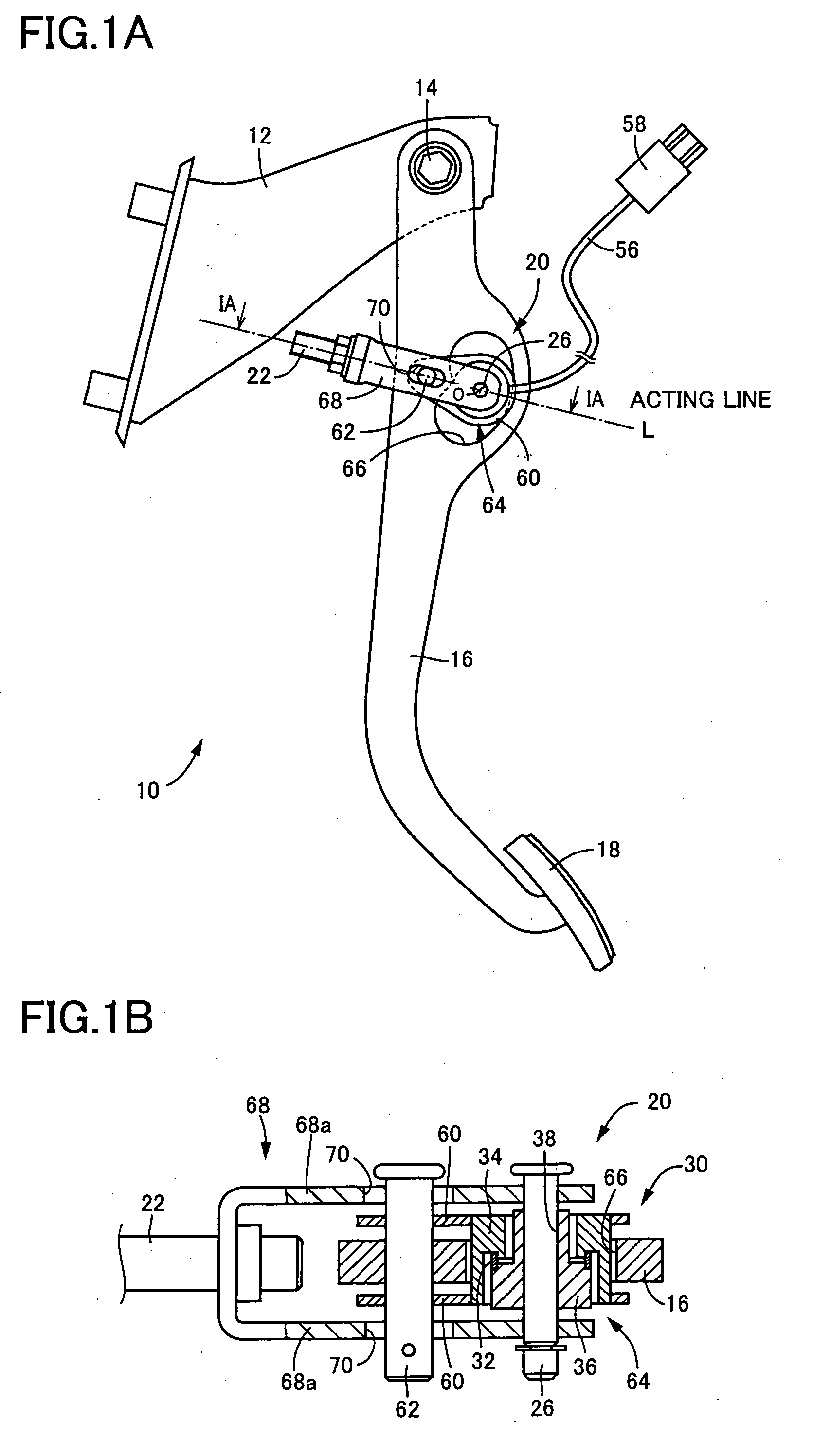
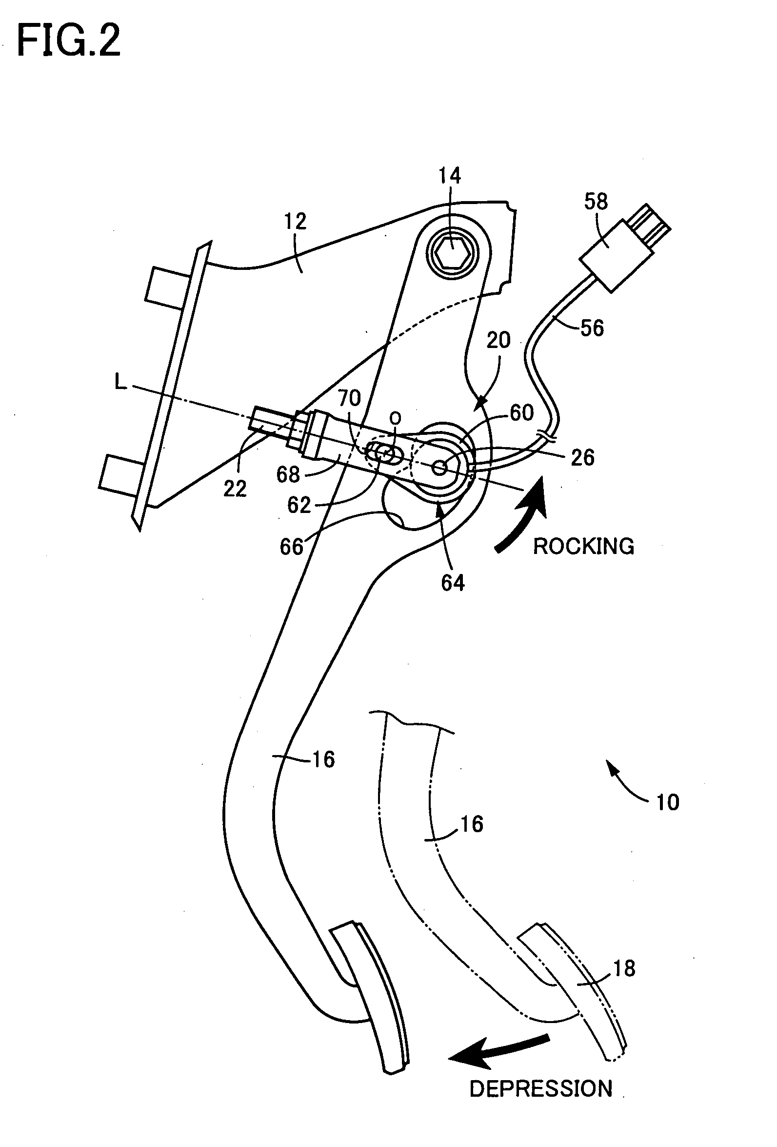
[0080]FIGS. 1A and 1B show an exemplary operating pedal apparatus 10 for a vehicle service brake according to one embodiment of the present invention. FIG. 1A is a front view of the operating pedal apparatus, and FIG. 1B is an enlarged cross-sectional view taken along the line IA-IA in FIG. 1A. The vehicle operating pedal apparatus 10 corresponds to a case where the present invention is applied to the aforementioned operating pedal apparatus 200 shown in FIG. 16. One end of each of the transmittal links 60 is connected to an operational pedal 16 via a connecting pin 62 so that the transmittal links 60 are pivotable relative to the operational pedal 16 about the connecting pin 62, which is in parallel to a support shaft 14. At the other end of each of the transmittal links 60, a load sensor 64 is arranged. A sensor accommodating hole 66, having an arc shape that centers on th...


PUM


Abstract

This invention relates to a load sensor-equipped operating apparatus, which comprises an operational member (16) which is movably operated; a reaction force member (22) which receives an operating force of the operational member transmitted thereto, and on which a reaction force corresponding to the operating force is acted; at least one pivotal connecting portion (20) which is interposed between the operational member and the reaction force member, and pivotably connects a pair of a first member and a second member relative to each other to transmit the operating force; and a load sensor (30) which electrically detects the operating force. The load sensor-equipped operating apparatus is characterized by that the load sensor includes a shaft-like member (36), a main body member (34) disposed to be relatively displaced in a direction perpendicular to an axis of the shaft-like member, a deformable member (32) bridging the shaft-like member and the main body member, and a strain detecting element (40a to 40d) which is secured to the deformable member, and the shaft-like member and the main body member are relatively displaced by the reaction force in the direction perpendicular to the axis of the shaft-like member to deform the deformable member so that the strain detecting element detects the deformation of the deformable member; a transmittal link (60), one end of which is connected to the first member by a connecting pin, and other end of which is integrally secured to one of the shaft-like member and the main body member of the load sensor; other of the shaft-like member and the main body member of the load sensor is connected to the second member; and the connecting pin is arranged, in a front view of the load sensor as viewed in the axial direction, on an acting line of the load which is applied to the load sensor associating with a movable operation of the operational member, at a position generating tensile force in the transmittal link, so that a pivotal movement of the transmittal link about the connecting pin or the load sensor associating with the movable operation of the operational member maintains the direction of relative displacement between the shaft-like member and the main body member of the load sensor constant.

Description

[0001]The present application is based on Japanese Patent Application No. 2007-156606 filed in Japan, the content of which is incorporated herein by way of reference.BACKGROUND OF THE INVENTION[0002]1. Field of the Invention[0003]The present invention relates to an operating apparatus such as a vehicle operating pedal apparatus, and in particular to improvements to a load sensor-equipped operating apparatus that includes a load sensor which electrically detects operating force.[0004]2. Description of Related Art[0005]A load sensor-equipped operating apparatus is known which includes (a) an operational member which is movably operated; (b) a reaction force member that receives the operating force of the operational member transmitted thereto, and on which a reaction force corresponding to the operating force is acted; (c) at least one pivotal connecting portion which is located between the operational member and the reaction force member, and connects a pair of the members pivotably ...

Claims


Application Information

Patent Timeline
IPC IPC(8): G05G1/14B60T7/02B60T7/06G01L5/22G05G1/30G05G1/38
CPCG01L1/2237Y10T74/20528G01L5/225
Inventor FUJIWARA, NOBORU
Owner TOYODA IRON WORKS CO LTD
Why Eureka
Try Eureka