Camera System And Mechanical Apparatus
- Summary
- Abstract
- Description
- Claims
- Application Information
AI Technical Summary
Benefits of technology
Problems solved by technology
Method used
Image

Examples
first embodiment
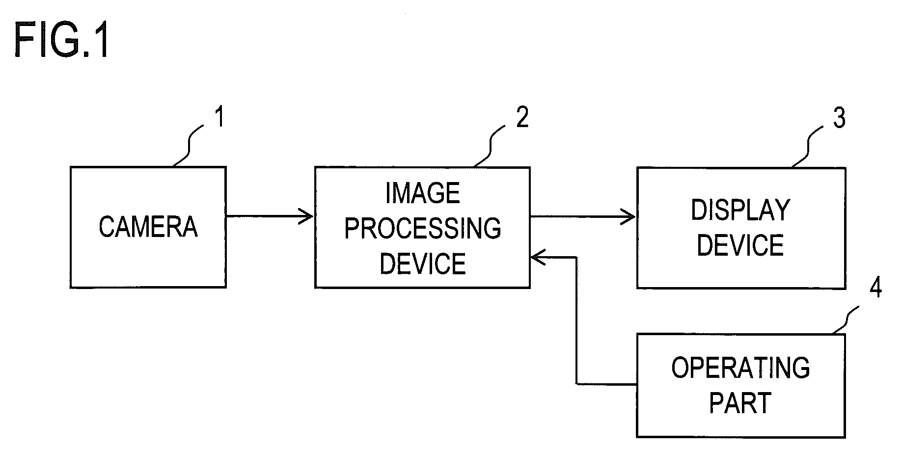
[0042]A first embodiment of the present invention will be described with reference to FIGS. 1, 2A and 2B. FIG. 1 is a general block diagram of a visibility assisting system according to the first embodiment. The visibility assisting system shown in FIG. 1 includes a camera 1, an image processing device 2, a display device 3 and an operating part 4.
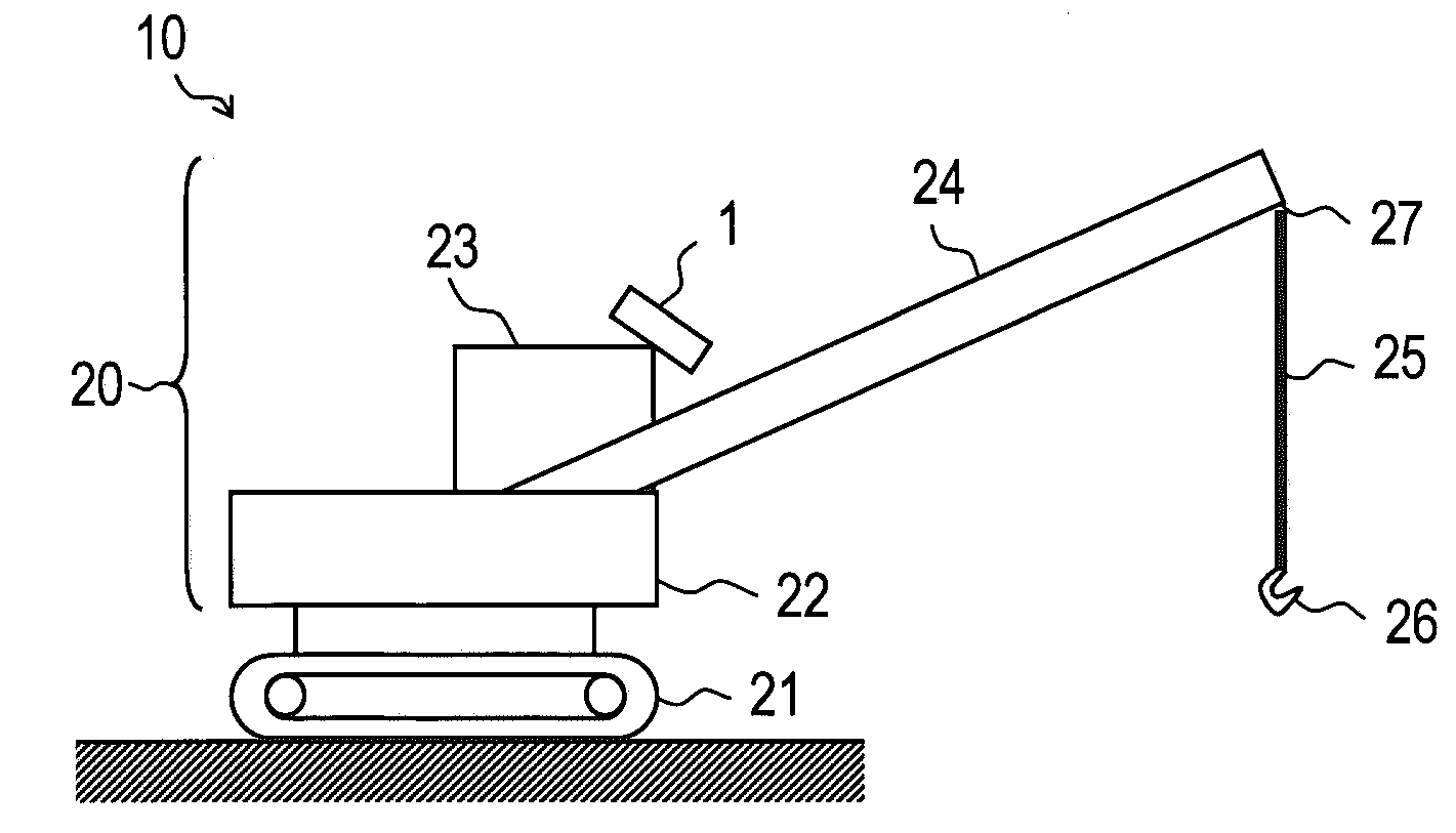
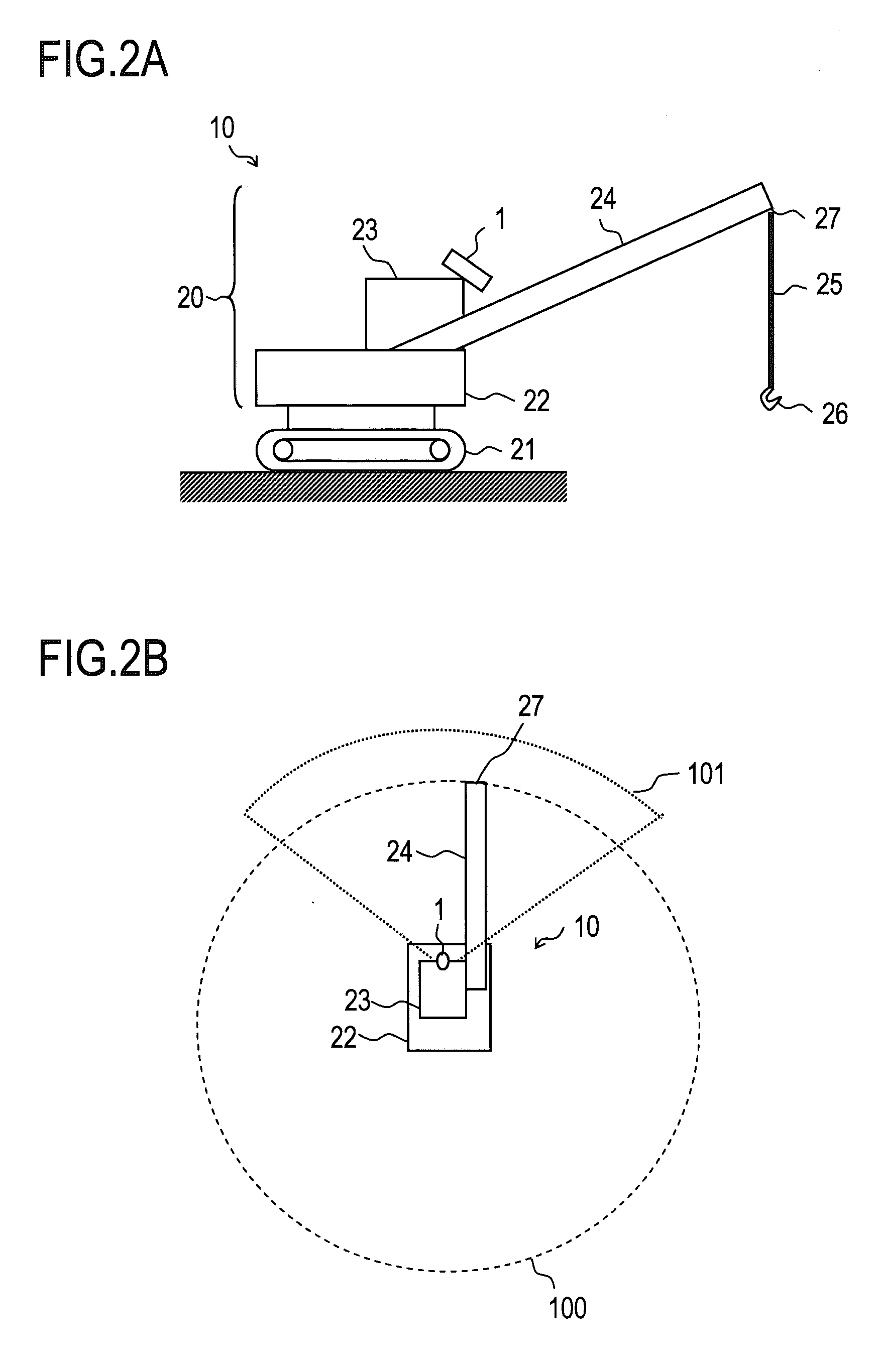
[0043]FIG. 2A is a side view showing an appearance of a crane mechanical apparatus 10 equipped with the visibility assisting system shown in FIG. 1, and FIG. 2B is a plan view of the crane mechanical apparatus 10 viewed from above.
[0044]The crane mechanical apparatus 10 is a movable crane, which is exemplified by a crawler crane in the present embodiment. The crane mechanical apparatus 10 includes a lower running gear 21 (hereinafter referred to as a running gear 21 simply) as the crawler, an upper rotating table 22 (hereinafter referred to as a rotating table 22 simply), a cockpit box 23, and a boom 24. In addition, the crane mechanical a...
second embodiment
[0081]Next, a second embodiment of the present invention will be described. A general block diagram of the visibility assisting system according to the second embodiment and the crane mechanical apparatus 10 to which the visibility assisting system is applied are the same as those in the first embodiment. The operating procedure of the visibility assisting system in the second embodiment is different from that in the first embodiment, but other structure is the same between the first and the second embodiments. Therefore, the description will be described only about the operating procedure. The description that is described above in the first embodiment can be also applied to the second embodiment as long as no contradiction arises.
[0082]The operating procedure of the visibility assisting system according to the second embodiment will be described with reference to FIG. 10. FIG. 10 is a flowchart showing this operating procedure. Individual processes in steps S1 to S3 and S11 to S13...
third embodiment
[0091]Furthermore, if the bird's eye view image is displayed as described above in the second embodiment, it is possible to provide the image that can contribute to the safety assistance by performing a zoom adjustment of the bird's eye view image. In the real space, the security confirmation area is viewed as small from a high viewpoint while it is viewed as large from a low viewpoint. In the same manner if the height H of the virtual camera used in the steps S11 and S12 shown in FIG. 10 is changed, a display size of the security confirmation area can be changed freely.
[0092]An embodiment in which such a change is performed will be described as a third embodiment. The third embodiment is different partially from the second embodiment, so a difference between the third and the second embodiments will be described below. Other than the part that will be described particularly in the third embodiment are the same as those in the second embodiment. In addition, the description that is ...
PUM
 Abstract
Description
Claims
Application Information
 - Generate Ideas
- Intellectual Property
- Life Sciences
- Materials
- Tech Scout
- Unparalleled Data Quality
- Higher Quality Content
- 60% Fewer Hallucinations
Browse by: Latest US Patents, China's latest patents, Technical Efficacy Thesaurus, Application Domain, Technology Topic, Popular Technical Reports.
© 2025 PatSnap. All rights reserved.Legal|Privacy policy|Modern Slavery Act Transparency Statement|Sitemap|About US| Contact US: help@patsnap.com