Video camera and flicker reduction method in video camera

a technology of video camera and flicker reduction, which is applied in the direction of color television details, television systems, color signal processing circuits, etc., can solve the problems of insufficient reduction and degraded picture quality of video image output from a different video camera

Inactive Publication Date: 2008-12-18
ELMO CO LTD
View PDF7 Cites 32 Cited by
  • Summary
  • Abstract
  • Description
  • Claims
  • Application Information

AI Technical Summary

Benefits of technology

[0011]With this arrangement, the flicker reduction unit has a plurality of flicker reduction modes. Thus, by setting the flicker reduction mode appropriately, flicker reduction may by performed with a more appropriate method specific to the illumination conditions of the subject. Moreover, the video camera outputs a video signal which contains a settings screen for assisting selection of one of the flicker reduction modes, superimposed over the image of the subject. Thus, the user can set the flicker reduction mode while viewing the settings screen, making it easier to set a more appropriate flicker reduction mode.
[0013]With this arrangement, a video signal which includes a superimposed settings screen for assisting selection of the flicker reduction mode is output in instances where the commercial power frequency is one that could possibly cause flicker. Thus, in instances where flicker may possibly occur making it advisable to set the flicker reduction mode, the user is prompted to set the flicker reduction mode thereby making it easier to set a more appropriate flicker reduction mode.
[0015]With this arrangement, an order of precedence is established for the respective flicker reduction modes on the basis of characteristics of the video signal. The flicker reduction mode may be switched according to this order of precedence. This makes it easier to set a more appropriate flicker reduction mode.

Problems solved by technology

For this reason, it may sometimes occur that, flicker is not sufficiently reduced with a certain video camera under the conditions of the illuminating light source, while the picture quality of the video image output from a different video camera may degrade due to an excessive flicker reduction.

Method used


Image

  • Video camera and flicker reduction method in video camera
  • Video camera and flicker reduction method in video camera
  • Video camera and flicker reduction method in video camera

Examples


first embodiment

A. First Embodiment

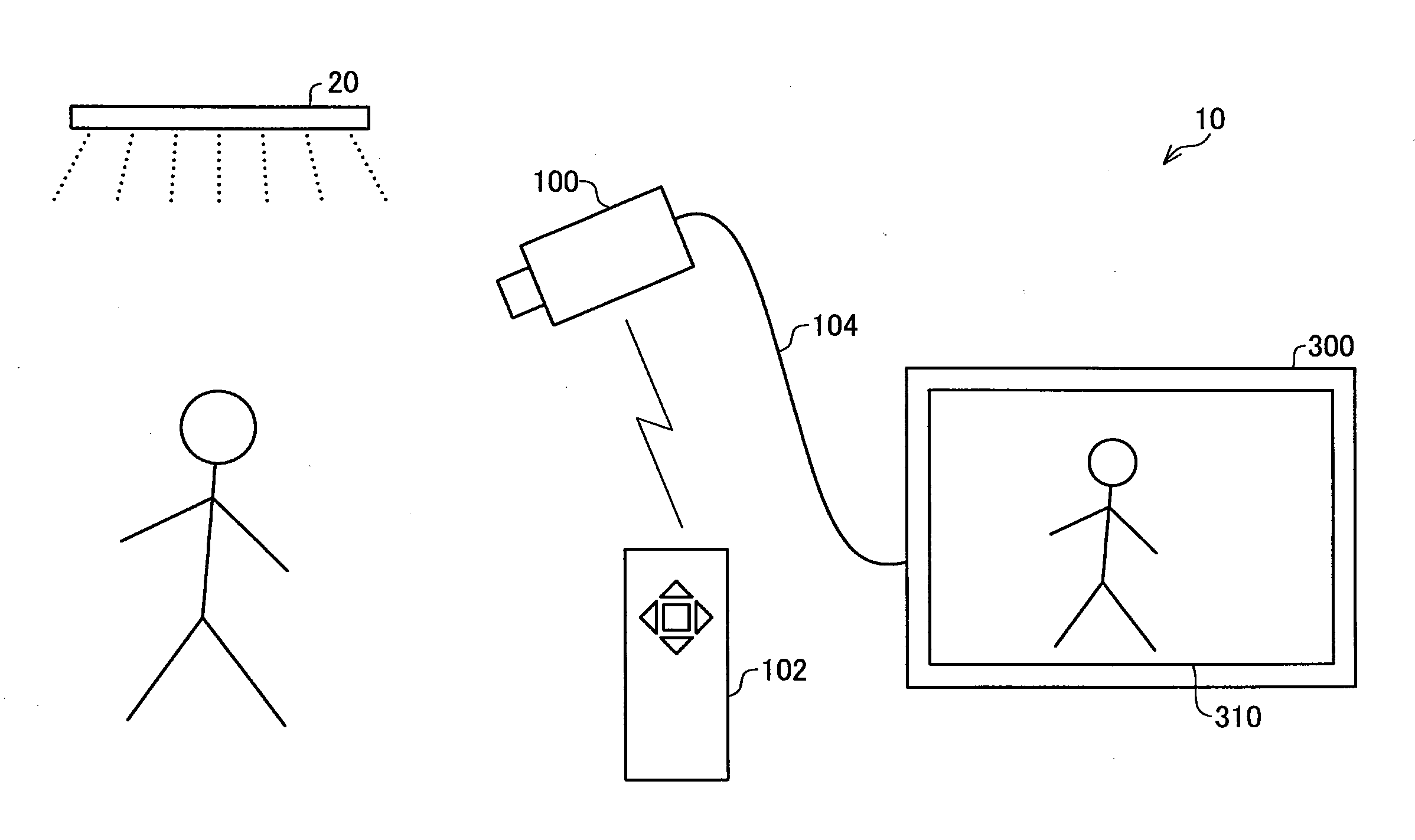
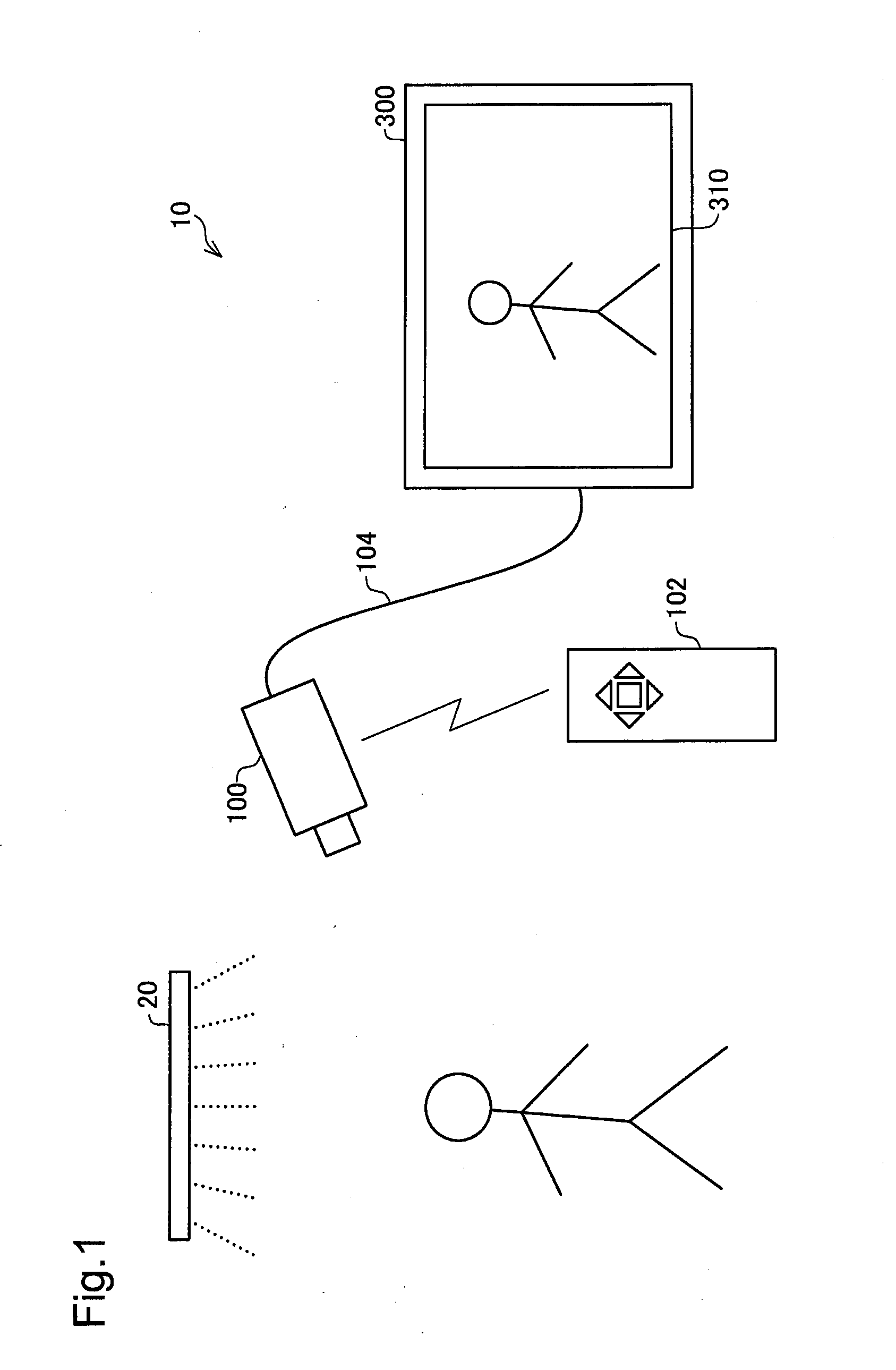
[0032]FIG. 1 is a schematic diagram showing a configuration of a monitoring system implementing a first embodiment. The monitoring system 10 includes a video camera 100 equipped with a remote controller 102, and a video monitor 300. The user of the monitoring system 10 is able to make settings of the video camera 100 through operation of buttons provided on the remote controller 102.

[0033]The video camera 100 of the monitoring system 10 shoots an area illuminated by a fluorescent lamp 20 (illuminated area). The video image shot by the video camera 100 is supplied to the video monitor 300 through a cable 104. The video monitor 300 displays the supplied video image on a screen 310. In the example of FIG. 1, as a subject a human within the illuminated area of fluorescent lamp 20 is shot by the video camera 100. Thus, a video image including this person is displayed on the screen 310 of the video monitor 300.

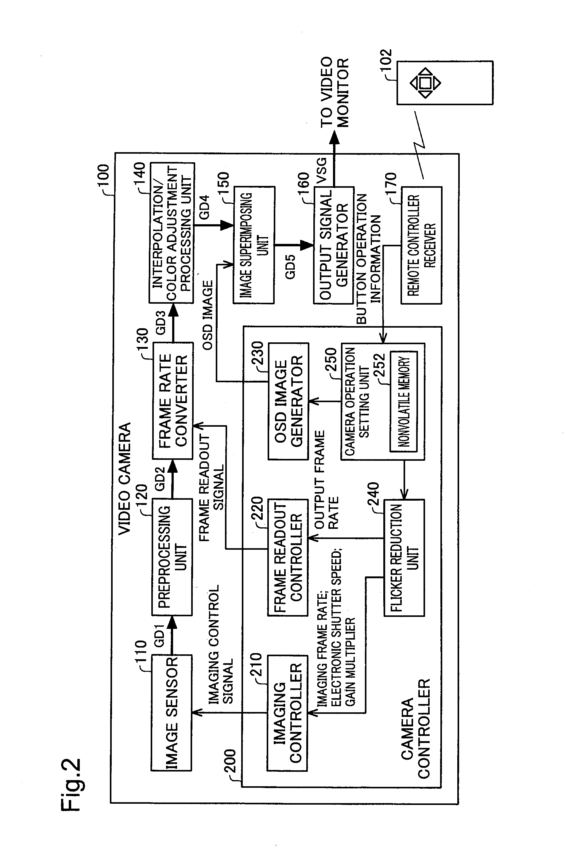
[0034]FIG. 2 is a functional block diagram showing the funct...

second embodiment

B. Second Embodiment

[0085]FIG. 13 is a block diagram showing the functional configuration of a video camera 100a in a second embodiment. The video camera 100a of the second embodiment differs from the video camera 100 of the first embodiment in that the former is equipped with a commercial power frequency detection unit 180, and a camera operation setting unit 250a is connected to this commercial power frequency detection unit 180. In other aspects it is similar to the video camera 100 of the first embodiment.

[0086]The commercial power frequency detection unit 180 detects the commercial power frequency of the region in which the video camera 100a is situated. Specifically, it detects whether the frequency of the power supplied to the video camera 100a is 50 Hz or 60 Hz. Detection of commercial power frequency can be accomplished through the use of a frequency counter, a detector employing a band pass filter, or similar device. The detection result of commercial power frequency with ...


PUM


Abstract

To reduce flicker appropriately according to illumination condition of an imaging subject, a video camera is provided. The video camera includes an imaging unit for generating a subject image; a superimposing image generator for generating a superimposing image; an image synthesizer for synthesize the subject image and the superimposing image to generate a synthesized image; a video signal generator for generating a video signal from the synthesized image so as to display the synthesized image. The video camera also includes a flicker reduction unit to reduce flicker caused by luminance fluctuation of a light source. The flicker reduction unit has a plurality flicker reduction modes. The mode setting unit makes the superimposing image generator to generate a settings screen as the superimposing image for assisting selection of one of the flicker reduction modes.

Description

CROSS-REFERENCE TO RELATED APPLICATIONS[0001]The present application claims the priority based on Japanese Patent Application No. 2007-156488 filed on Jun. 13, 2007, the disclosure of which is hereby incorporated herein by reference in its entirety.BACKGROUND[0002]1. Field of the Invention[0003]This invention relates to a technique for reducing flicker of image shot with a video camera caused by luminance fluctuation of an illuminating light source.[0004]2. Description of the Related Art[0005]The frequency of commercial electrical power is standardized at either 50 Hz or 60 Hz depending on geographical region. Depending on the type of lighting equipment, the luminance of a lighting equipment which uses such commercial electrical power fluctuates at a frequency equal to the frequency of commercial electrical power (commercial power frequency) or a twice of the commercial power frequency. For example, in regions of 50 Hz commercial power frequency, the luminance of an incandescent lam...

Claims


Application Information

Patent Timeline
Patent Type & Authority Applications(United States)
IPC IPC(8): H04N5/217H04N9/73H04N5/225H04N5/235
CPCH04N5/23293H04N5/235H04N5/2357H04N23/633H04N23/70H04N23/745
Inventor NISHIWAKI, KATSUHIRONAGATSUMA, HIROSHIMASUI, YASUONAKAMURA, TADAMASA
Owner ELMO CO LTD
Why Eureka
Try Eureka