Method and System for Optoelectronic Detection and Location of Objects

a technology of optoelectronic detection and location, applied in the field of optoelectronic sensors, can solve the problems of label not being printed, and potentially costly mistakes, and achieve the effects of avoiding adverse effects on production process, avoiding potential cost, and avoiding potential cost overruns

Active Publication Date: 2008-12-18
COGNEX CORP
View PDF99 Cites 25 Cited by
  • Summary
  • Abstract
  • Description
  • Claims
  • Application Information

AI Technical Summary

Benefits of technology

[0029]advanced ability to distinguish desired objects from other conditions, based on measurements made in one-dimensional images, including embodiments that use normalized correlation pattern detection methods and processes;
[0054]In an illustrative embodiment, accurate location information with no latency is obtained by predicting the time at which an object will cross a reference point, and scheduling a signal to occur at the predicted time. The prediction is obtained by fitting a curve, for example a line, through a set of (time, position) points, where the times correspond to times at which images were captured and the positions are obtained from image measurements.

Problems solved by technology

If a bottle is not detected, however, its label will not be printed, a potentially costly mistake.
If a signal is produced when no bottle is present, the printer may spray ink into the air, which may have adverse effects on the production process.
However, if the objects to be detected are reflective, misdetection and / or mislocation errors may occur.
This makes it easier to detect objects whose positions are not well constrained, but decreases the precision of the location at which objects are detected and increases the chances that a detection will occur when no desired object is in front of the beam.
No sensor is a perfect judge of object presence and location, and failures will result if a desired object is not detected, if some other condition, such as an unexpected object or light source, results in a false detection, or if a desired object is detected but mislocated.
Photoelectric sensors are well-suited to object detection and location, and are widely used, but they have a variety of limitations.
Such sensors have a very limited ability to distinguish desired objects from other conditions such as unexpected objects, variations in object reflectivity, confusing markings or features on the objects, and the like.
This limits the ways in which such sensors can be installed, the nature of objects to be detected and located, and the manner in which such objects are presented to the sensor, among other concerns.
Furthermore, generally only edges of objects can be detected and located; it is difficult and in many cases impractical to detect and locate markings or other features on the object.
Such an adjustment is challenging to make and may have undesirable consequences if not made carefully.
Furthermore, it is difficult to establish a reference point with high precision.
Photoelectric sensors have an inherent delay between the time that an object crosses the reference point and the time that the signal transition occurs.
If the latency and velocity are known it may be possible to compensate for the latency, but doing so adds complexity and cost, and might not always be practical.
The less time the sensor has to make a detection decision, the less reliable the decision will be.
The combination of physical positioning, latency, and repeatability limit the accuracy of a photoelectric sensor in locating objects.
These devices, however, exhibit significant latency, on the order of several milliseconds, and repeatability that, even under favorable conditions, is no better than that of photoelectric sensors.
Vision detectors, furthermore, are very expensive compared to photoelectric sensors, and far more complex to set up for a given application.

Method used


Image

  • Method and System for Optoelectronic Detection and Location of Objects
  • Method and System for Optoelectronic Detection and Location of Objects
  • Method and System for Optoelectronic Detection and Location of Objects

Examples


Embodiment Construction

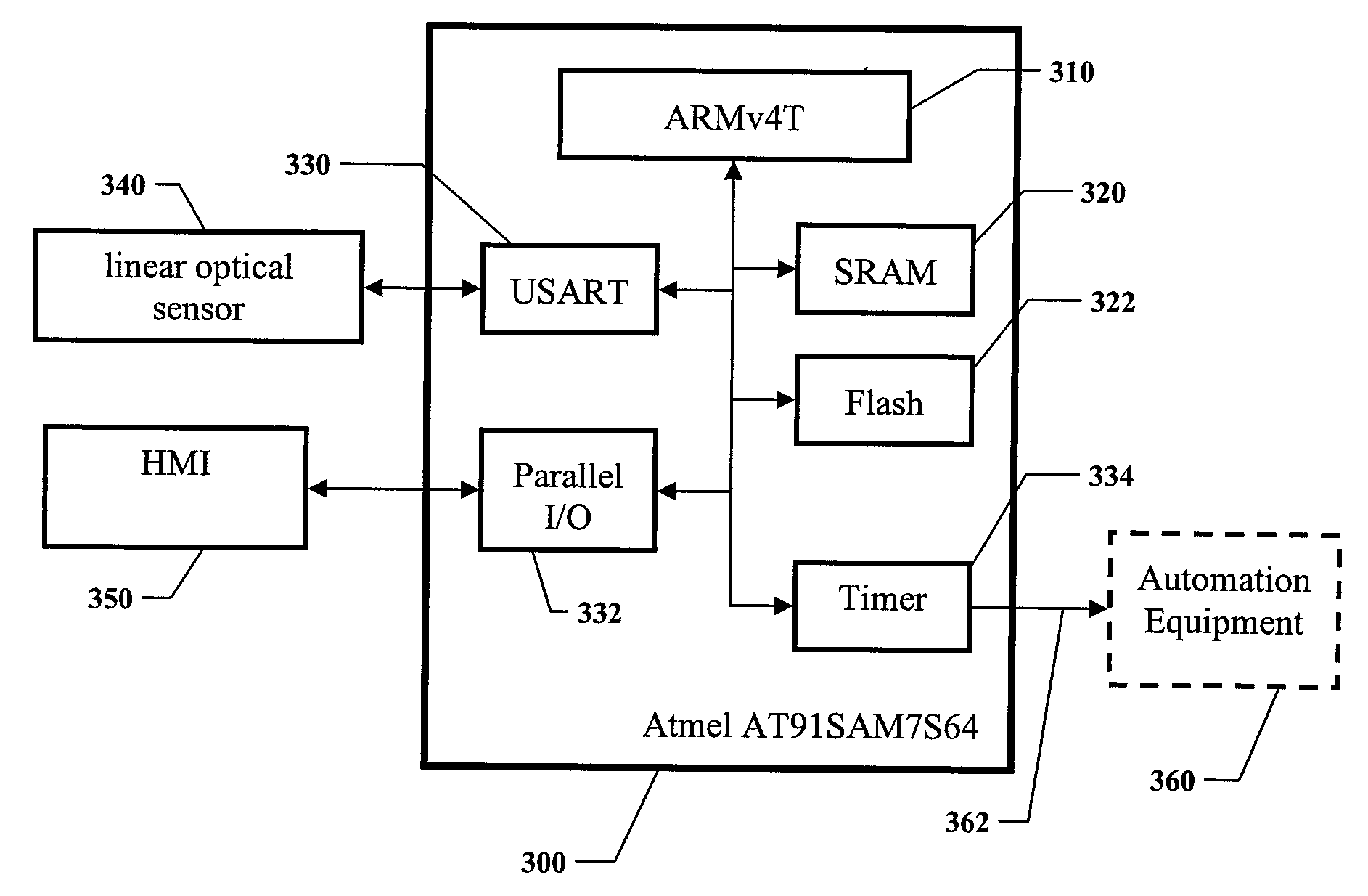
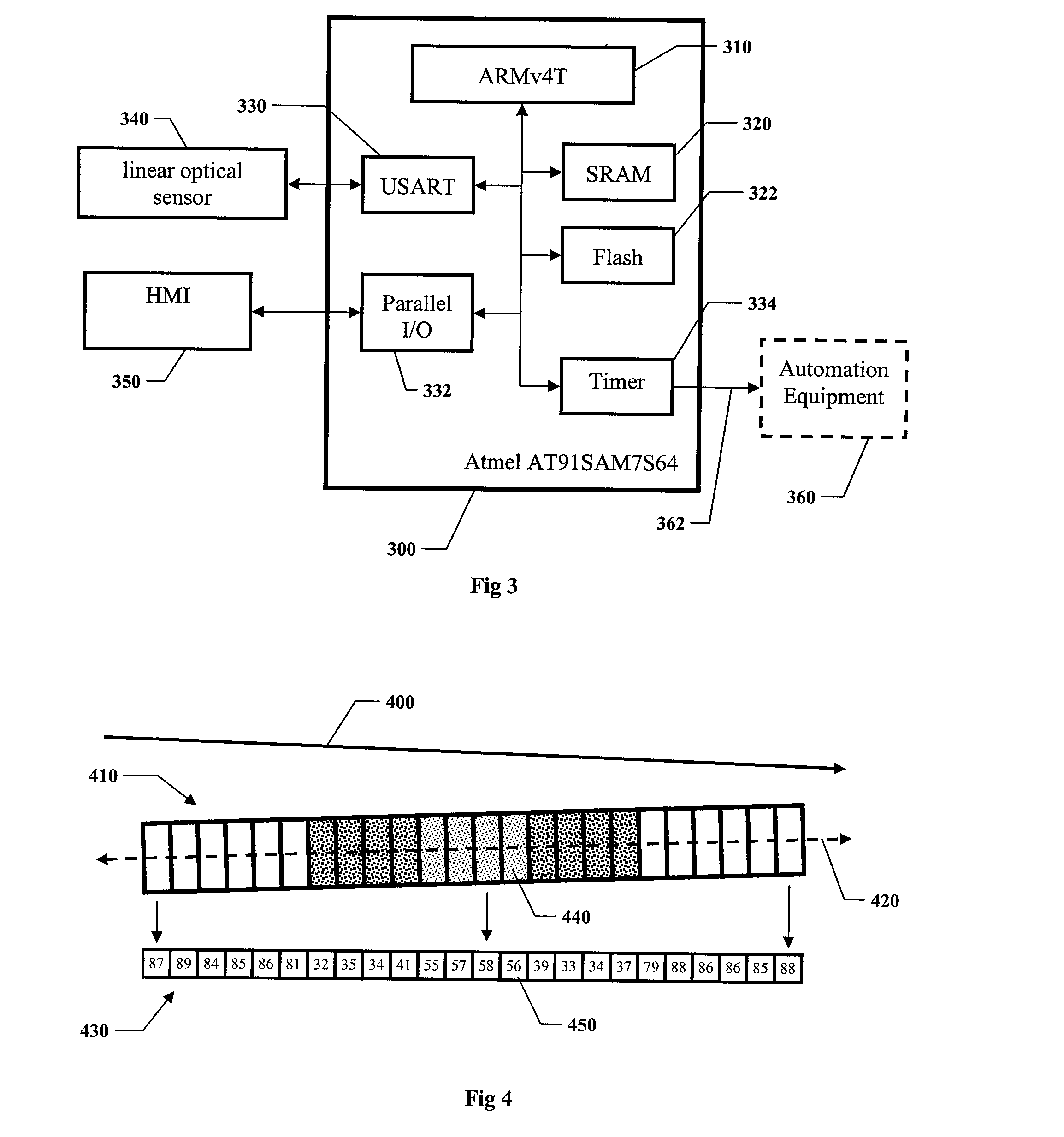
[0074]In the following detailed description of the illustrative embodiments, reference is made to the accompanying drawings which form a part hereof, and in which are shown by way of illustration specific embodiments in which the invention may be practiced. It is to be understood that other embodiments may be utilized and structural changes may be made without departing from the scope of the invention.

Some Definitions

[0075]As used herein the term linear detector refers to an optoelectronic system according to an embodiment of the invention, for purposes of providing information describing objects, herein equivalently referred to as object information. Similarly, the term linear detection method refers to a method according to an embodiment of the invention for like purposes.

[0076]Applications of a linear detector include but are not limited to analysis, detection, and location of objects. In an illustrative embodiment intended for object detection, the object information comprises k...


PUM

PropertyMeasurementUnit
distanceaaaaaaaaaa
distanceaaaaaaaaaa
clock frequencyaaaaaaaaaa

Abstract

Disclosed are methods and systems for optoelectronic detection and location of moving objects. The disclosed methods and systems capture one-dimensional images of a field of view through which objects may be moving, make measurements in those images, select from among those measurements those that are likely to correspond to objects in the field of view, make decisions responsive to various characteristics of the objects, and produce signals that indicate those decisions. The disclosed methods and systems provide excellent object discrimination, electronic setting of a reference point, no latency, high repeatability, and other advantages that will be apparent to one of ordinary skill in the art.

Description

FIELD OF THE INVENTION[0001]The invention relates to optoelectronic sensors for detecting objects and providing information describing the objects, particularly their location.BACKGROUND OF THE INVENTION[0002]Optoelectronic sensors for detecting and locating objects are valuable in a wide variety of fields; one example is industrial automation. In order to understand the operation, capabilities, and limitations of such sensors, consider a specific example application-printing alphanumeric characters on labels in a high-speed production bottling line. In a typical such application, a sensor detects the presence of a bottle at a predetermined point as it moves down the production line, and produces a signal that tells a printer to start printing when a bottle is located at that point.[0003]If a signal is produced when a bottle is at the proper location, desired alphanumeric characters are printed on the bottle's label in a desired location. If a bottle is not detected, however, its la...

Claims


Application Information

Patent Timeline
Patent Type & Authority Applications(United States)
IPC IPC(8): G01N21/00
CPCG01S5/16G06T2207/30108G06T7/20G06T7/004G06T7/70
Inventor SILVER, WILLIAM M.
Owner COGNEX CORP
Why Eureka
Try Eureka