Thermoelectric methods to control temperature of batteries

Active Publication Date: 2008-12-18
GM GLOBAL TECH OPERATIONS LLC
View PDF21 Cites 109 Cited by
  • Summary
  • Abstract
  • Description
  • Claims
  • Application Information

AI Technical Summary

Benefits of technology

[0007]One embodiment of the invention includes thermoelectric methods which are suitable to control the temperature of batteries in a variety of applications. The methods include providing a thermoelectric device; providing a battery in thermally-conductive contact with the thermoelectric dev

Problems solved by technology

This results in a short battery lifespan and degraded battery performance.
On the other hand, low battery temperatures encountered during c

Method used


Image

  • Thermoelectric methods to control temperature of batteries
  • Thermoelectric methods to control temperature of batteries
  • Thermoelectric methods to control temperature of batteries

Examples


Example

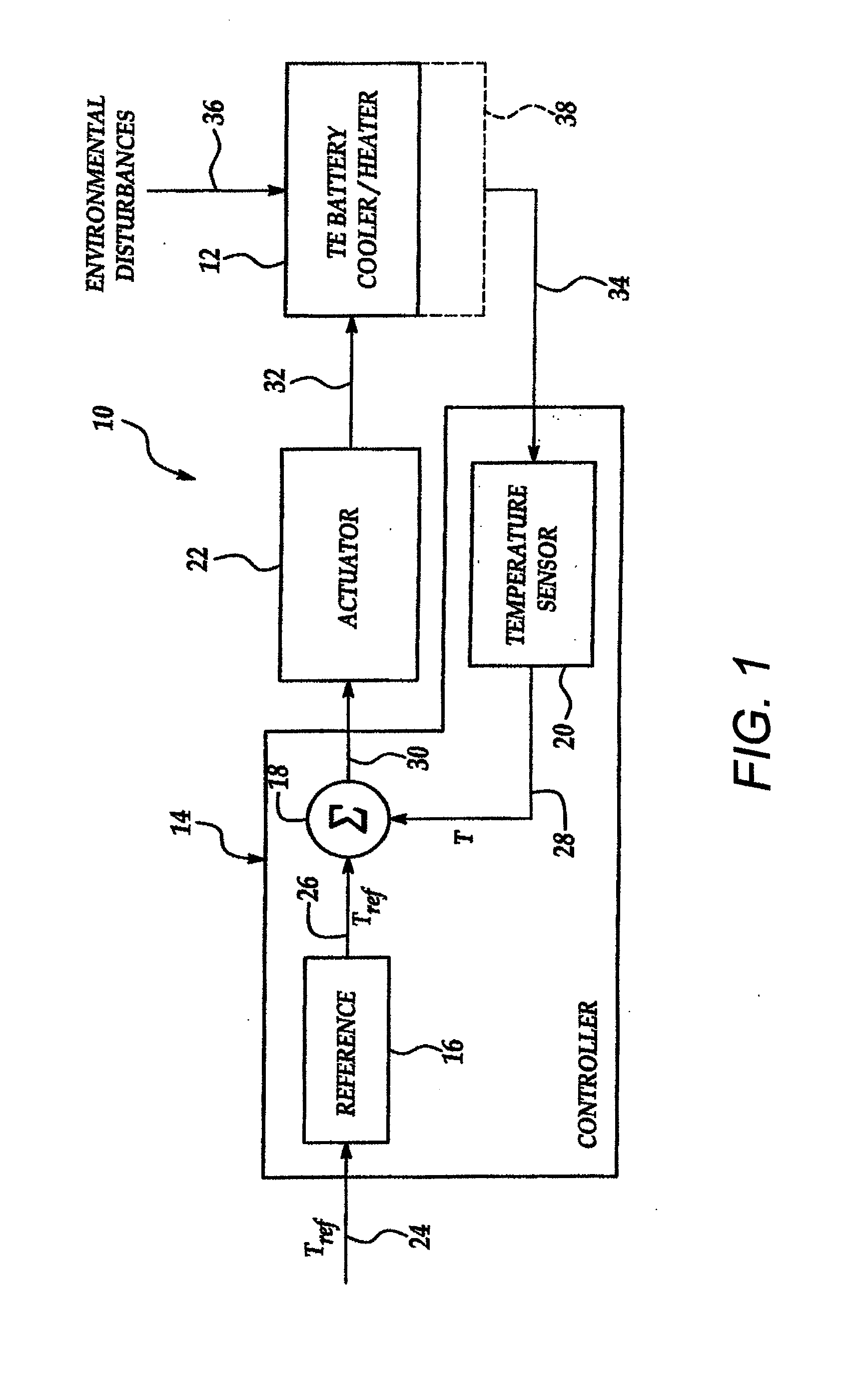
[0024]Referring initially to FIG. 1, an illustrative embodiment of a thermoelectric (TE) battery control system, hereinafter system, according to the present invention is generally indicated by reference numeral 10. The system 10 includes a thermoelectric (TE) device 12 having a conventional Peltier circuit (not shown). Responsive to flow of electrical current in one direction through the Peltier circuit, heat is generated at one side and absorbed at the opposite side of the TE device 12. When current flows in the opposite direction through the Peltier circuit, the hot and cold sides of the TE device 12 are reversed.

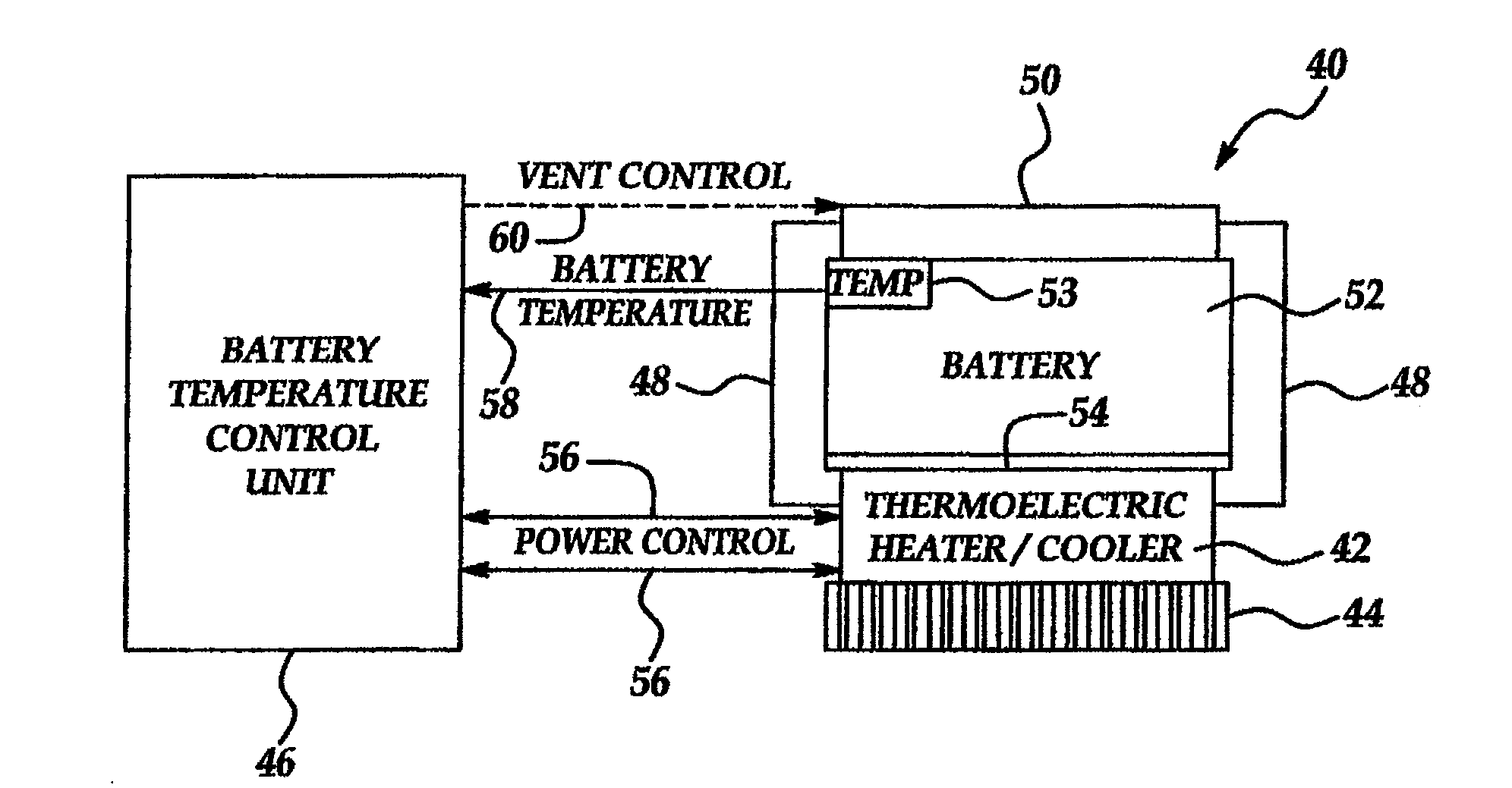
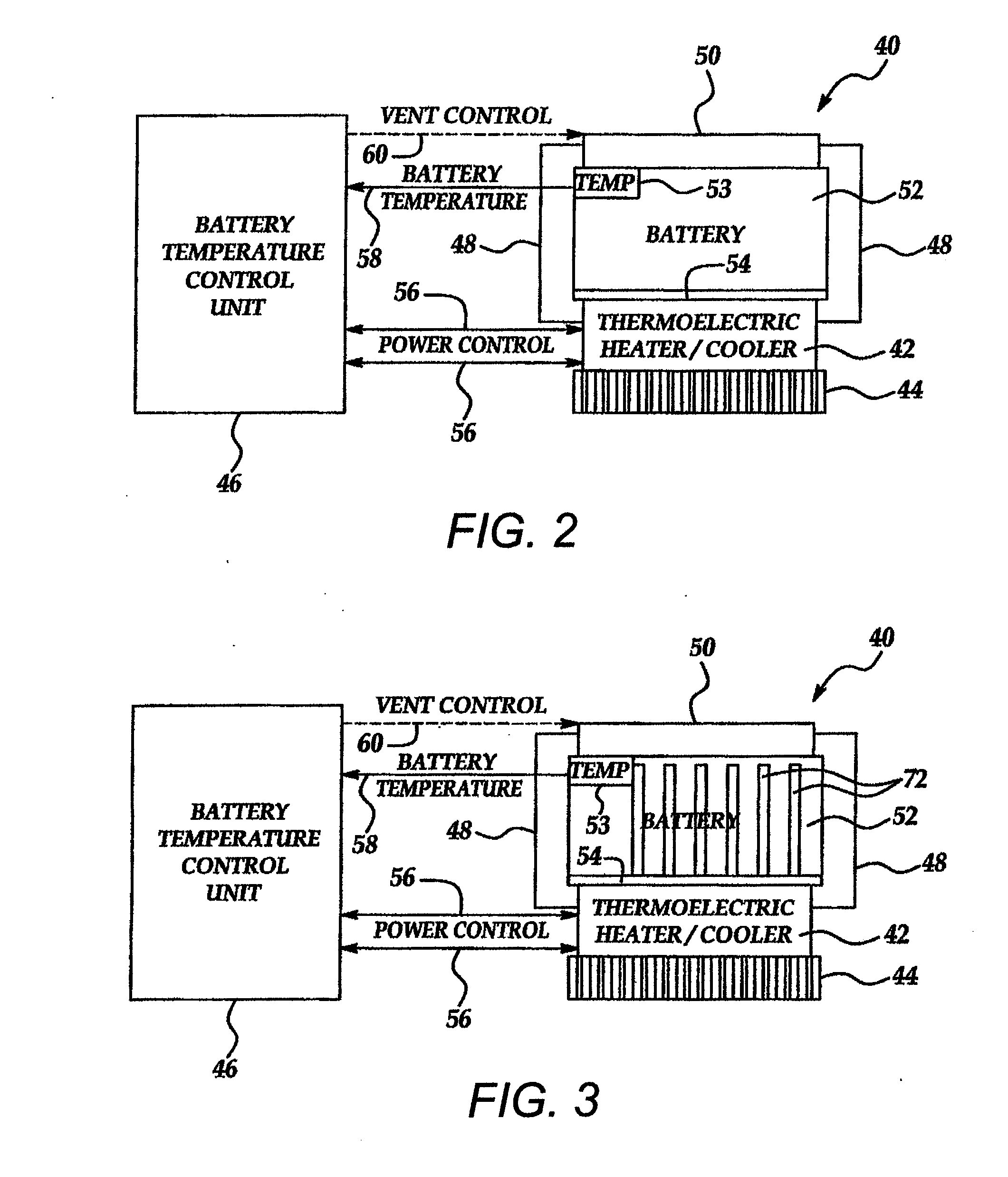
[0025]A battery 38, such as an automotive battery, for example, is provided in thermally-conductive contact with one side of the TE device 12. The battery 38 may be any type of battery including but not limited to a lead acid battery, a nickel metal hydride battery or a lithium ion battery. Furthermore, the TE device 12 can be arranged in any desired configuration with r...


PUM


Abstract

A method of controlling a temperature of a battery is disclosed. The method includes providing a thermoelectric device in thermally-conductive contact with the battery, measuring an actual temperature of the battery, comparing the actual temperature of the battery to a reference temperature for the battery, heating the battery by operation of the thermoelectric device when the actual temperature is less than the reference temperature and cooling the battery by operation of the thermoelectric device when the actual temperature exceeds the reference temperature.

Description

CROSS-REFERENCE TO RELATED APPLICATIONS[0001]This application is a continuation-in-part of U.S. patent application Ser. No. 10 / 739,789 filed Dec. 18, 2003, a continuation-in-part of U.S. patent application Ser. No. 11 / 028,836 filed Jan. 4, 2005 and claims the benefit of U.S. Provisional Application Ser. No. 60 / 590,879 filed Jul. 23, 2004.FIELD OF THE INVENTION[0002]The present invention relates to thermoelectric devices which utilize electrical power to generate a thermal gradient. More particularly, the present invention relates to methods of controlling the temperature of batteries by using thermoelectric devices to cool or heat the batteries, as needed.BACKGROUND OF THE INVENTION[0003]Thermoelectric (TE) technology has attracted worldwide interest in recent years. TE devices can be used for cooling and electrical power generation purposes in a variety of applications. While much of the work in thermoelectric technology has focused on the development of new thermoelectric material...

Claims


Application Information

Patent Timeline
IPC IPC(8): H01M10/50
CPCH01M10/486H01M10/5004H01M10/5087H01M10/5022H01M10/5085H01M10/5006H01M10/615H01M10/633H01M10/6572H01M10/613H01M10/658Y02E60/10
Inventor YANG, JIHUILEDBETTER, KELLY B.STABLER, FRANCIS R.SCOTT, DAVID S.
Owner GM GLOBAL TECH OPERATIONS LLC
Why Eureka
Try Eureka