Multifocal Iol

a multi-focal, iol technology, applied in the field of intraocular lenses, can solve the problems of large opening, difficult to implant a lens system of this type into the eye, and difficulty in obtaining the desired movement of two or more lenses

Inactive Publication Date: 2008-12-18
OCULENTIS HLDG
View PDF11 Cites 35 Cited by
  • Summary
  • Abstract
  • Description
  • Claims
  • Application Information

AI Technical Summary

Benefits of technology

[0008]The aim of the present invention is to provide an IOL with which switching from one optical field to another optical field, such as a near part and a distance part, is possible in a simple way.

Problems solved by technology

However, it has been found that the movement of the ciliary muscle is relatively restricted, making it difficult to obtain the desired movement of the two or more lenses of the lens system.
Moreover, it is not easy to implant a lens system of this type into the eye through a very small opening.
This means that a larger opening has to be made with inevitable lengthening of the recovery time of the patient.
Therefore lenses of this type have not been generally introduced to date.

Method used


Image

  • Multifocal Iol
  • Multifocal Iol
  • Multifocal Iol

Examples


Embodiment Construction

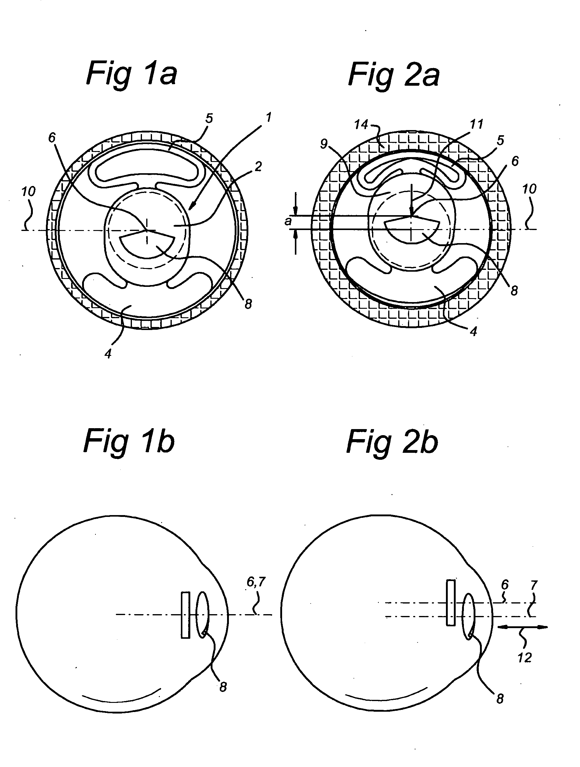
[0030]In FIG. 1 and more particularly FIG. 1a an intraocular lens is indicated in its entirety by 1. This consists of a lens part 2 where so-called haptics or supporting parts 4 and 5 are provided on opposite sides. In the present case two supporting parts located opposite one another are illustrated. It should be understood that, instead of two, there may be three or more supporting parts.

[0031]In the present illustrative embodiment the supporting part 5 has been made elastically deformable, while the supporting part 4 is rigid. The lens part 2 has an optical centre 6 and a horizontal longitudinal centre line 10. A distance part 9 and a reading part 8 are delimited in the lens part. The reading part 8 extends between 120 and 160 degrees.

[0032]The distance of the supporting parts 4 and 5 from the outer periphery is made such that when the haptic is not contracted the optical axis 7 of the eye coincides with the optical centre 6 of the lens. This is illustrated in FIG. 1b. Consequent...


PUM


Abstract

Intraocular lens consisting of a centrally located lens part with supporting parts (haptics) on either side. According to the invention one supporting part is non-deformable and another supporting part, located approximately opposite said supporting part, is deformable. In this way it is achieved that when the ciliary cell contracts the reduction in the space therein is used for moving the centre of the lens part. By arranging the transition between distance and near part in a multifocal lens on said centre, switching from the distance part to the near part can be obtained for the user in an almost natural way.

Description

BACKGROUND OF THE INVENTION[0001]The present invention relates to an intraocular lens (IOL) comprising a lens part with a centre, which lens part is provided on the periphery with two supporting parts (haptics). Lenses of this type are generally known in the state of the art. These are used for replacement of the eye lens after cataract operations, for example. For a large number of people an attempt is made to provide both a distance part and a near part (reading part) in these lenses. According to the state of the art this is obtained with the aid of mechanisms which act on the haptics and by which, when a lens system is used, the two or more lenses of such a system are moved in the axial direction. That is to say, the radial movement of the haptics is converted via a mechanism into an axial movement of the lenses. The focal length of the lens system can be changed by bringing two lenses linked one behind the other further apart or closer together and it is possible to provide a d...

Claims


Application Information

Patent Timeline
Patent Type & Authority Applications(United States)
IPC IPC(8): A61F2/16
CPCA61F2/1613A61F2/1618A61F2/1632A61F2/1648A61F2250/0018
Inventor WANDERS, BERNARDUS FRANCISCUS MARIA
Owner OCULENTIS HLDG
Why Eureka
Try Eureka