Femoral head calcar loading prosthesis

a femoral head and loading prosthesis technology, applied in the field of orthopedic surgery, can solve the problems of patient deterioration, fracture, and subsequent revision, and achieve the effects of improving patient function, reducing patient pain, and improving patient comfor

Inactive Publication Date: 2008-12-18
CONCEPT DESIGN & DEV
View PDF3 Cites 19 Cited by
  • Summary
  • Abstract
  • Description
  • Claims
  • Application Information

AI Technical Summary

Benefits of technology

[0010]The present invention meets the above identified need by providing a novel hip replacement implant system that includes a ball assembly having a ball trunion or trunion, the ball assembly being con

Problems solved by technology

This design typically places unnatural stresses on the femur, which lead to pain and the consequent curtailment of activity for the patient.
In addition to imposing unnatural stresses on portions of the femur, the negative effects of stress shielding of the portions of the femoral bone that normally carry the load transfer can result in bone weakness, fractures, and the need for subsequent revisions.
It is also possible that with conventional hip replacement surgery the resulting leg length can be changed from the natural length, which can induce further gait, balance, back, and other problems for the patient.
Because of the inducement of additional problems including subsequent hip fractures, the current designs of hip prosthesis often have a useful life less than that of the patient.
This is particularly a problem for active, young patients.
The isthmus provides a reproducible area for locking of the implant; however, by intrusively violating the femoral canal the options for revision surgery at a future date are limited.
If revision surgery is required, it usually involves implanting a longer femoral prosthesis into the canal, a technique that is more difficult and less reproducible.
Total Hip Replacement requires conventional open surgical techniques with resultant blood loss, pain, and prolonged recovery periods.
Younger patients are more likely to have failure of their primary replacement procedure due to the increased mechanical demand of their active lifestyle and from a longer life expecta

Method used


Image

  • Femoral head calcar loading prosthesis
  • Femoral head calcar loading prosthesis
  • Femoral head calcar loading prosthesis

Examples


Embodiment Construction

[0023]Detailed embodiments of the present invention are disclosed herein; however, it is understood that the following description and each of the accompanying figures are provided as being exemplary of the invention, which may be embodied in various forms without departing from the scope of the claimed invention. Thus, the specific structural and functional details provided in the following description are non-limiting, but serve merely as a basis for the invention as defined by the claims provided herewith. The device described below can be modified as needed to conform to further development and improvement of materials without departing from the inventor's concept of the invention as claimed.

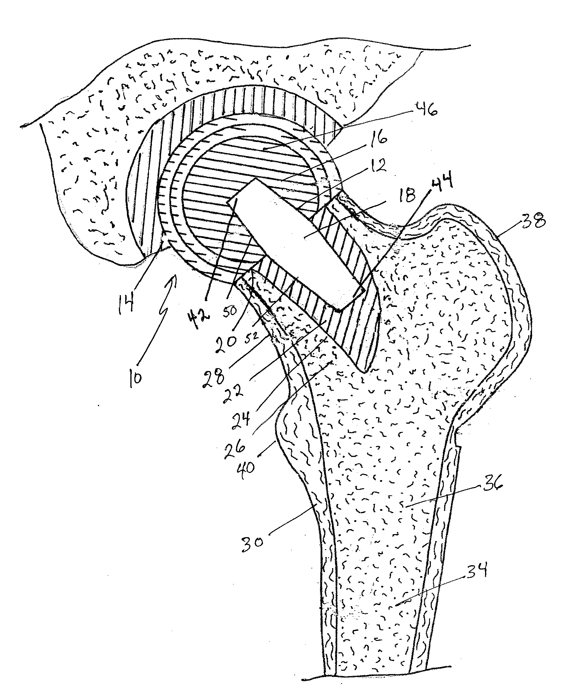
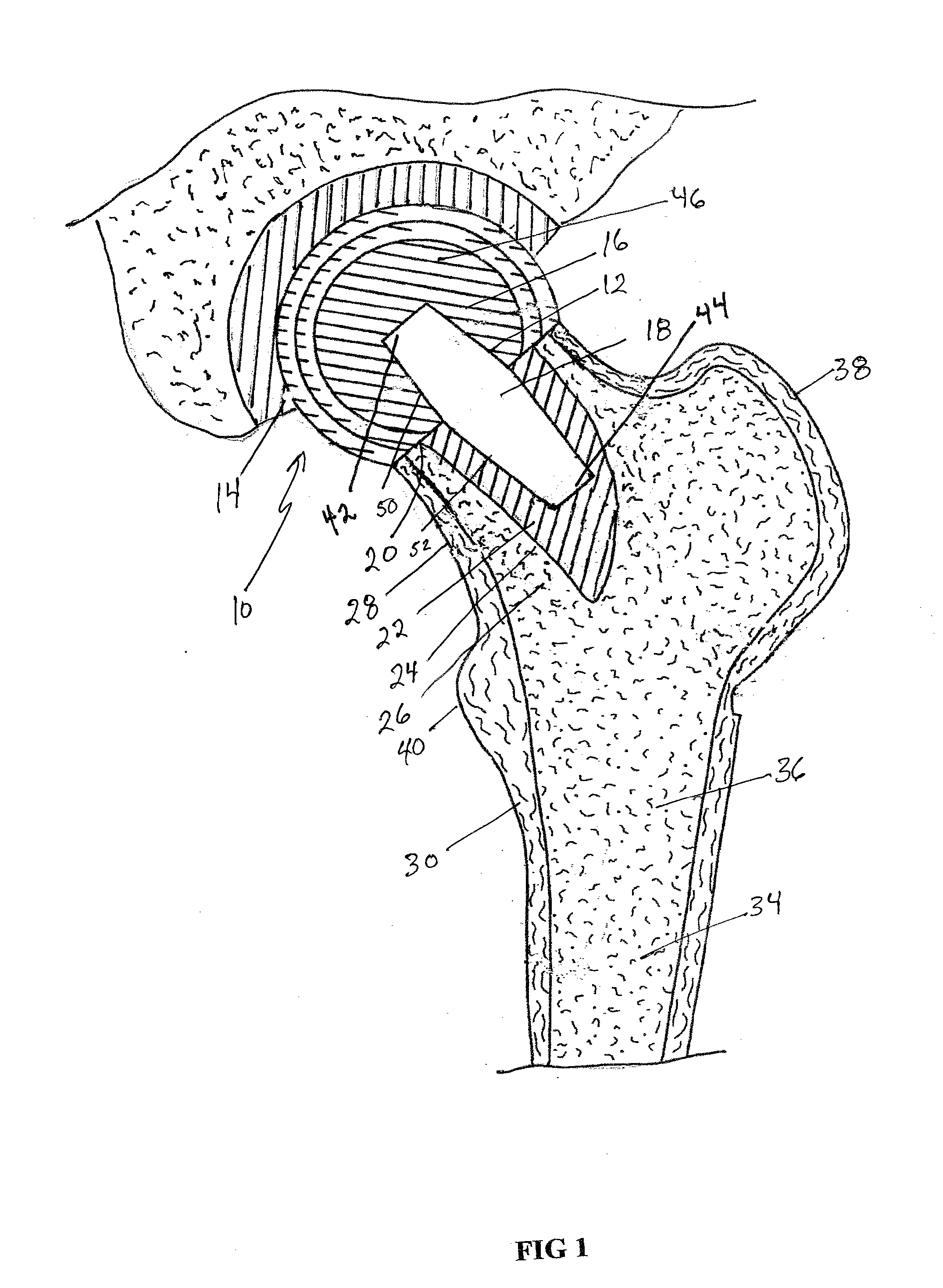
[0024]The novel hip replacement implant system, as generally shown at 10 in FIG. 1 includes a femoral head calcar loading prosthesis 12 that articulates with an acetabulum replacement component 14. The femoral head calcar loading prosthesis 12 includes a ball assembly 16 and a ball assembly ...


PUM


Abstract

Provided is a novel hip replacement implant system that includes a ball assembly having a ball trunion, the ball assembly being configured as a replacement for the head of the femur and capable of being secured by the ball assembly trunion to a calcar implant element that can be securely seated in the calcar bone of the femoral neck, thus maintaining the load transfer function of the calcar bone of the femoral neck. A method of using the device is also provided.

Description

BACKGROUND OF THE INVENTION[0001]1. Technical Field[0002]The present invention relates to orthopedic surgery and in particular to the provision and implantation of a novel hip prosthesis. More particularly the present invention relates to a novel femoral neck hip prosthesis that is implanted into the femoral neck and is coupled to the calcar bone of the femoral neck.[0003]2. Background Art[0004]In the United States approximately 500,000 hip replacements are performed on patients with hip arthritis. As the population ages and increases the number of hip replacement procedures can be expected to increase by 10 percent per year over the next decade.[0005]The majority of hip replacements have conventionally included the replacement of the proximal portion of the femur with an elongate, often curved shaft that extends into the medullary canal of the femur. This design typically places unnatural stresses on the femur, which lead to pain and the consequent curtailment of activity for the p...

Claims


Application Information

Patent Timeline
IPC IPC(8): A61F2/32A61F2/28A61F2/38
CPCA61F2/34A61F2/3601A61F2002/30125A61F2002/30153A61F2002/30332A61F2002/30616A61F2002/3082A61F2002/30879A61F2002/3092A61F2002/365A61F2002/3652A61F2002/4631A61F2220/0033A61F2230/0008A61F2230/0019
Inventor UNGER, ANTHONY S.
Owner CONCEPT DESIGN & DEV
Why Eureka
Try Eureka