
Simulation apparatus and simulation method

a simulation apparatus and simulation technology, applied in the field of simulation apparatus and method, can solve the problems of poor simulation accuracy, limited emulatable circuit scale, and high time and cost requirements for correcting

Inactive Publication Date: 2008-12-18
KK TOSHIBA
View PDF15 Cites 18 Cited by
  • Summary
  • Abstract
  • Description
  • Claims
  • Application Information

AI Technical Summary

Benefits of technology

[0012]According to one aspect of the present invention, there is provided a simulation apparatus, comprising: a hardware emulator which includes a first CPU core as a simulation target, and a debug control unit; a software simulator which includes a second CPU core as a simulation target, and a clock generation unit which generates a clock and supplies the clock to the first CPU core and the second CPU core; and a debugger which debugs the first CPU core and the second CPU core and in which a clock disable condition is set, wherein upon determining that the clock disable condition set in said debugger is satisfied, said debug control unit outputs a clock disable signal, and upon receiving the clock disable signal, said clock generation unit stops generating the clock.
[0013]According to one aspect of the present invention, there is provided a simulation apparatus, comprising: a hardware emulator which includes a first CPU core as a simulation target, an emulator operation control unit which generates a clock and supplies the clock to the first CPU core, and a debug control unit; a software simulator which includes a second CPU core as a simulation target, a simulator operation control unit which generates a clock and supplies the clock to the second CPU core, and a cooperative operation control unit which cooperates an operation of said emulator operation control unit and that of said simulator operation control unit; and a debugger which debugs the first CPU core and the second CPU core and in which a clock disable condition is set, wherein upon determining that the clock disable condition set in said debugger is satisfied, said debug control unit outputs a clock disable signal, upon receiving the clock disable signal, said emulator operation control unit outputs an operation stop interrupt signal, and upon receiving the operation stop interrupt signal, said cooperative operation control unit outputs synchronization / control information to said emulator operation control unit and said simulator operation control unit so that said emulator operation control unit and said simulator operation control unit stop generating the clock.
[0014]According to one aspect of the present invention, there is provided a simulation method of executing simulation for debugging a first CPU core and a second CPU core by using a simulation apparatus including a hardware emulator which includes the first CPU core as a simulation target, and a debug control unit, a software simulator which includes the second CPU core as a simulation target, and a clock generation unit which generates a clock and supplies the clock to the first CPU core and the second CPU core, and a debugger which debugs the first CPU core and the second CPU core and in which a clock disable condition is set, comprising: causing the debug control unit to determine whether the clock disable condition set in the debugger is satisfied; and causing the clock generation unit to stop generating the clock when the debug control unit determines that the clock disable condition is satisfied.

Problems solved by technology

In a recent system LSI with a large scale, if a defect of architecture level is found after formation on a chip, much time and cost are necessary for correcting it.
However, the emulatable circuit scale is limited from the viewpoint of the scale and cost of the elements of a programmable device.
This changes the number of execution cycles between the CPU cores each time they stop at a breakpoint or the like, resulting in poor simulation accuracy.

Method used


Image

  • Simulation apparatus and simulation method
  • Simulation apparatus and simulation method
  • Simulation apparatus and simulation method

Examples


first embodiment

(1) First Embodiment

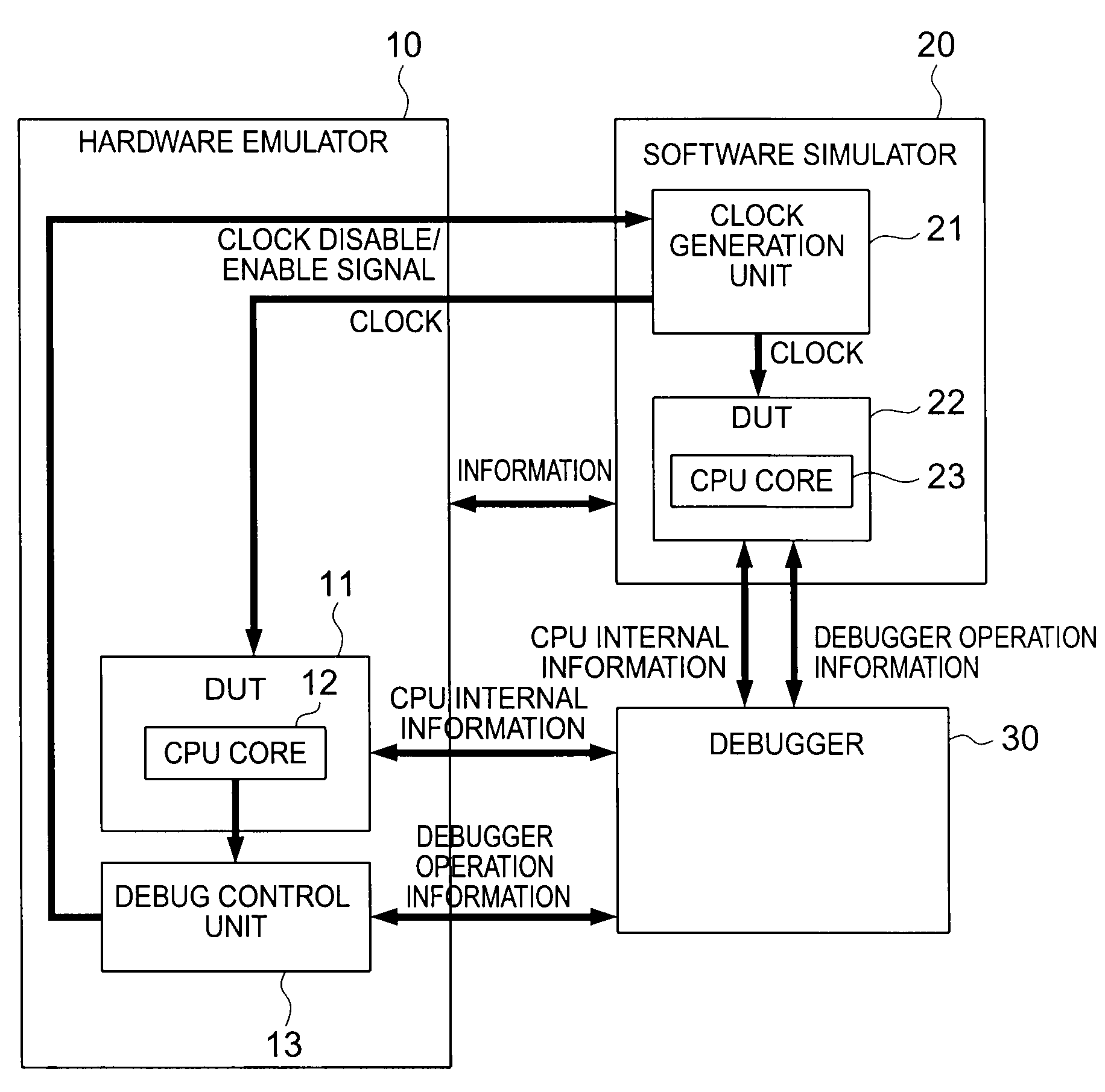
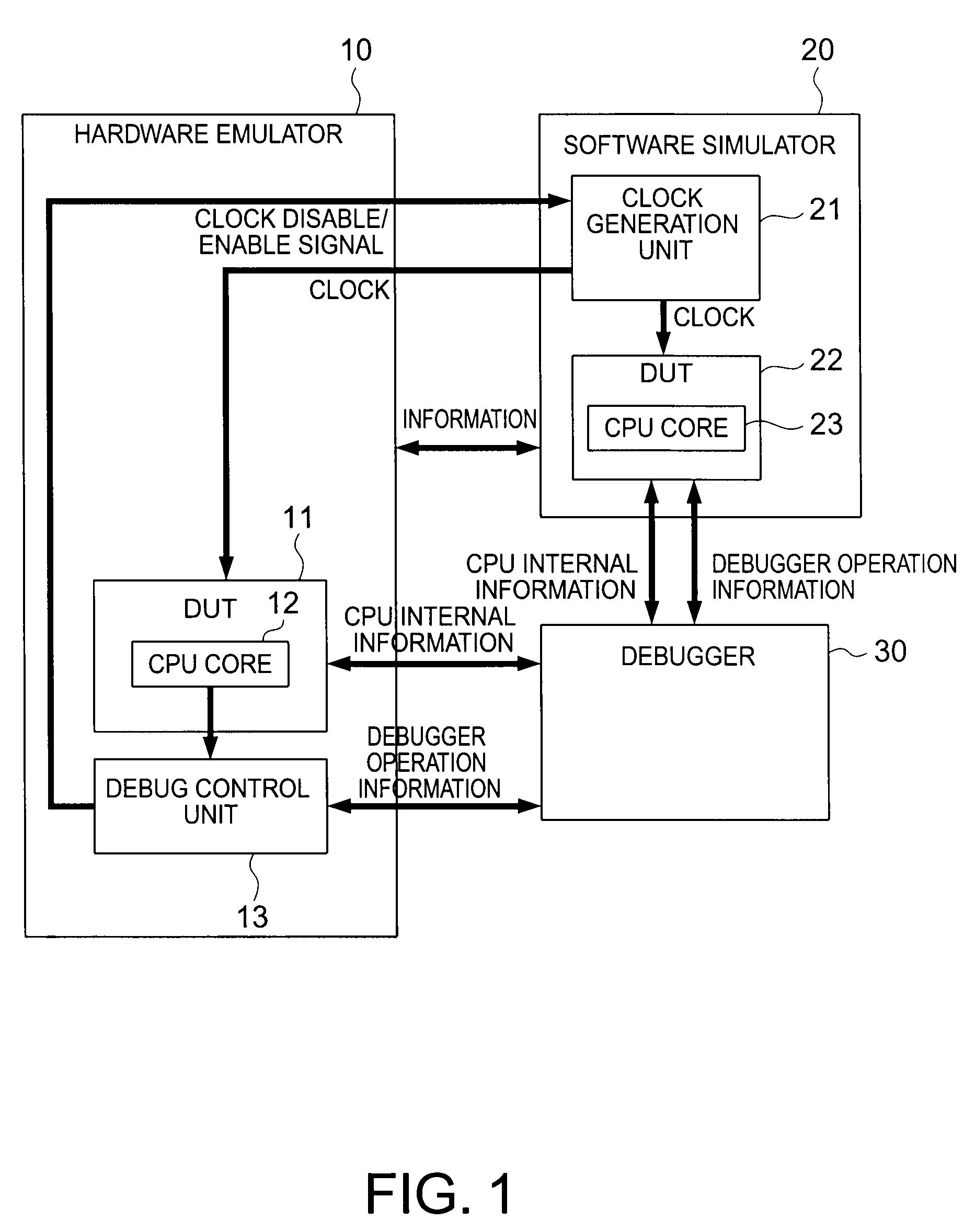
[0021]FIG. 1 shows the arrangement of a simulation apparatus according to the first embodiment of the present invention.

[0022]This simulation apparatus includes a hardware emulator 10, software simulator 20, and debugger 30.

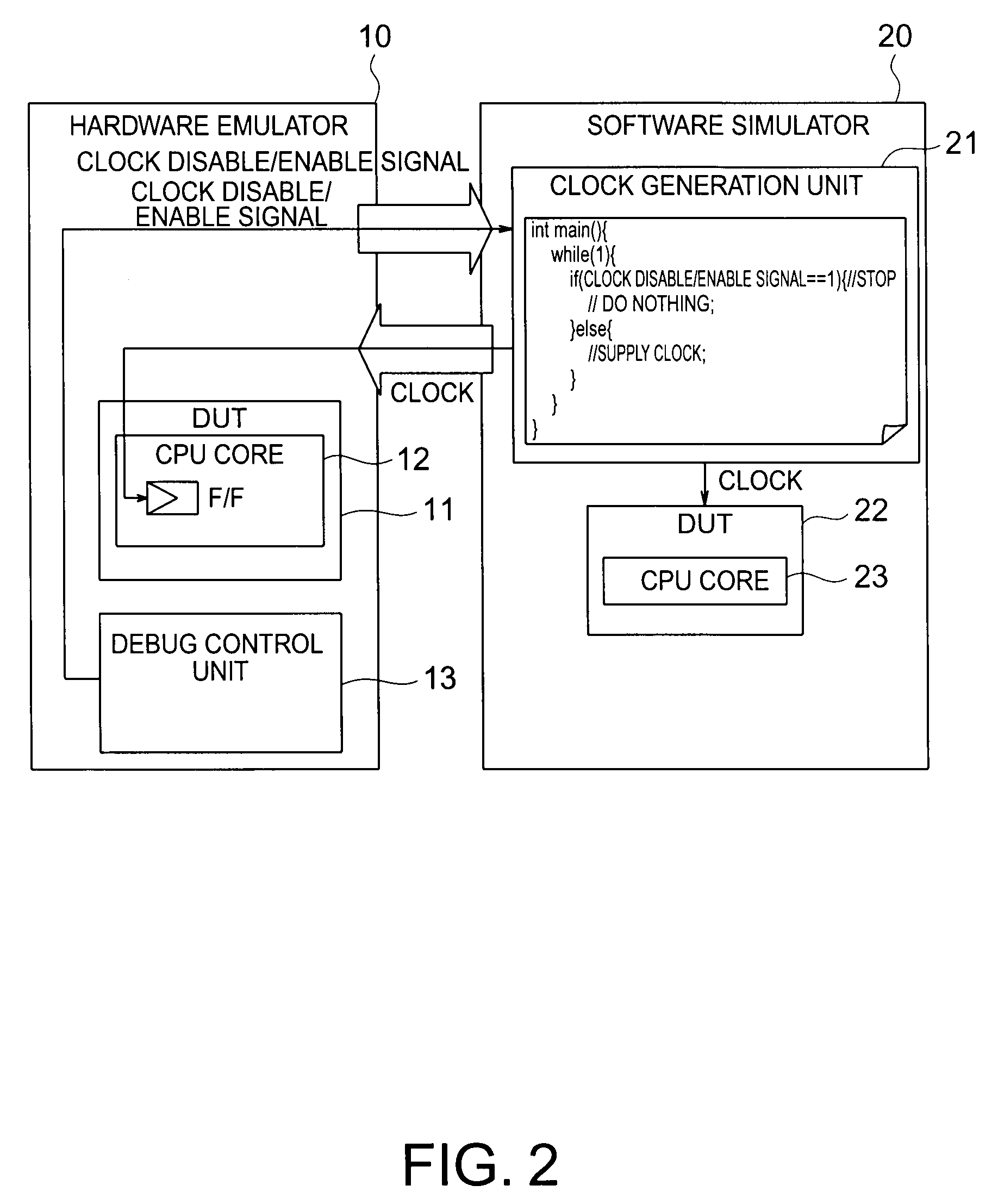
[0023]The hardware emulator 10 has a CPU core 12 serving as a DUT 11, and a debug control unit 13 which receives debugger operation information and transmits a clock disable / enable signal for disabling or enabling a clock to the software simulator 20. The software simulator 20 has a clock generation unit 21 which generates a clock, and a CPU core 23 serving as a DUT 22. The debugger 30 exchanges CPU internal information between the CPU cores 12 and 23 and also exchanges debugger operation information between the debug control unit 13 and the CPU core 23, thereby debugging the CPU cores 12 and 23.

[0024]The simulation apparatus performs cooperative simulation by operating the CPU core 12 in the hardware emulator 10 and the CPU core 23 in the sof...

second embodiment

(2) Second Embodiment

[0053]A simulation apparatus according to the second embodiment of the present invention will be described with reference to FIG. 5 that shows the arrangement.

[0054]In the first embodiment, only the clock generation unit 21 provided in the software simulator 20 generates the clock and supplies it to the CPU core 23 in the software simulator 20 and the CPU core 12 in the hardware emulator 10.

[0055]In the second embodiment, an emulator operation control unit 54 in a hardware emulator 50 generates a clock and supplies it to a CPU core 52 in the hardware emulator 50.

[0056]Additionally, a software simulator 60 incorporates a simulator operation control unit 61b which generates a clock to be supplied to a CPU core 63 in the software simulator 60. The software simulator 60 also incorporates a cooperative operation control unit 61a which synchronizes / cooperates the clock generation operation between the emulator operation control unit 54 and the simulator operation cont...


PUM


Abstract

According to the present invention, there is provided a simulation apparatus having, a hardware emulator which includes a first CPU core as a simulation target, and a debug control unit; a software simulator which includes a second CPU core as a simulation target, and a clock generation unit which generates a clock and supplies the clock to the first CPU core and the second CPU core; and a debugger which debugs the first CPU core and the second CPU core and in which a clock disable condition is set, wherein upon determining that the clock disable condition set in the debugger is satisfied, the debug control unit outputs a clock disable signal, and upon receiving the clock disable signal, the clock generation unit stops generating the clock.

Description

CROSS REFERENCE TO RELATED APPLICATION[0001]This application is based upon and claims benefit of priority under 35 USC §119 from the Japanese Patent Application No. 2007-159951, filed on Jun. 18, 2007, the entire contents of which are incorporated herein by reference.BACKGROUND OF THE INVENTION[0002]The present invention relates to a simulation apparatus and method and, more particularly, to a simulation apparatus and method which execute cooperative simulation between a hardware emulator and a software simulator.[0003]In a recent system LSI with a large scale, if a defect of architecture level is found after formation on a chip, much time and cost are necessary for correcting it. To prevent this, in developing a system LSI, the design quality and development efficiency are improved by reusing a block or module of a verified existing design or conducting stepwise verification based on a top-down design methodology. Such verification of system level requires a verification technology...

Claims


Application Information

Patent Timeline
Patent Type & Authority Applications(United States)
IPC IPC(8): G06F9/455
CPCG06F9/455G06F11/3632G06F11/3652G06F11/3656
Inventor AKIBA, TAKASHIMIURA, TAKASHI
Owner KK TOSHIBA
Learn More