
Mobile planter

a planter and mobile technology, applied in the field of planters, can solve the problems of small size, light weight, and inconspicuous visual appearan

Inactive Publication Date: 2008-12-25
NORVITCH DANIEL A
View PDF45 Cites 22 Cited by
  • Summary
  • Abstract
  • Description
  • Claims
  • Application Information

AI Technical Summary

Benefits of technology

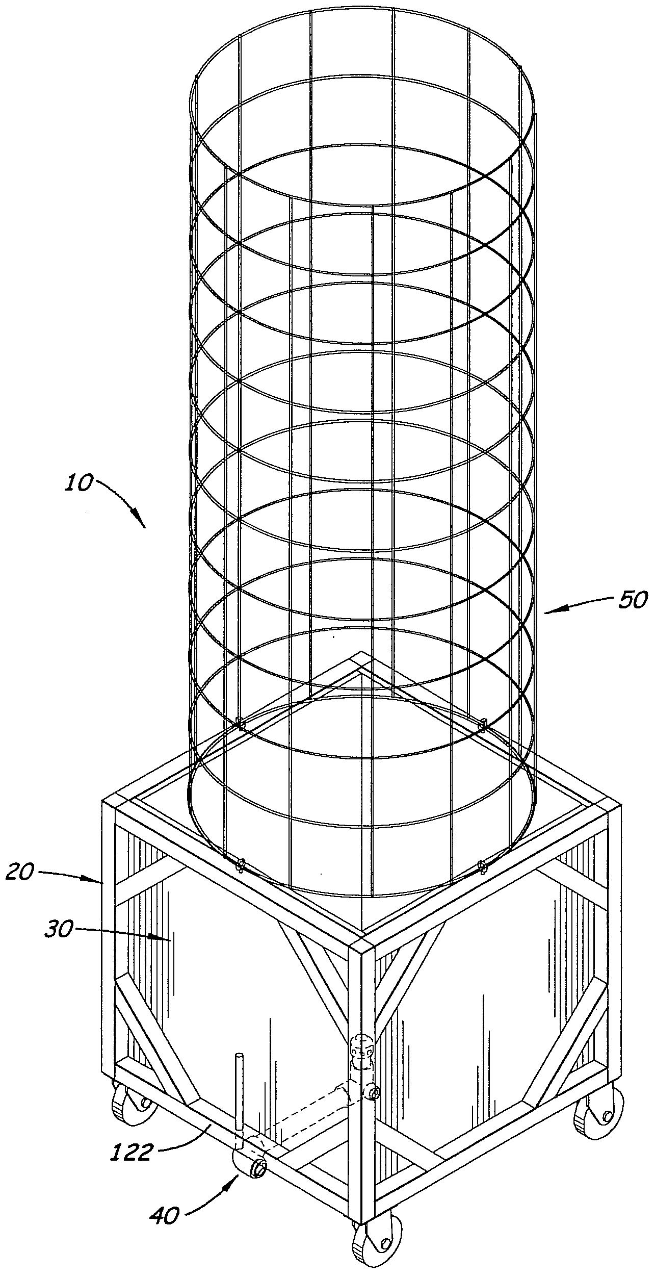
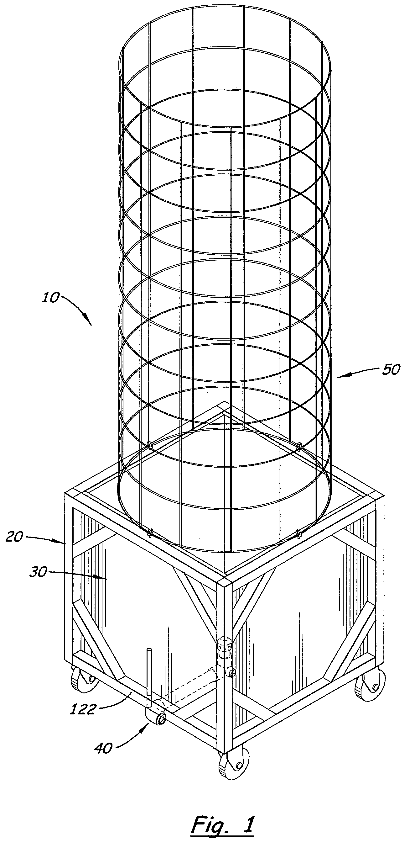
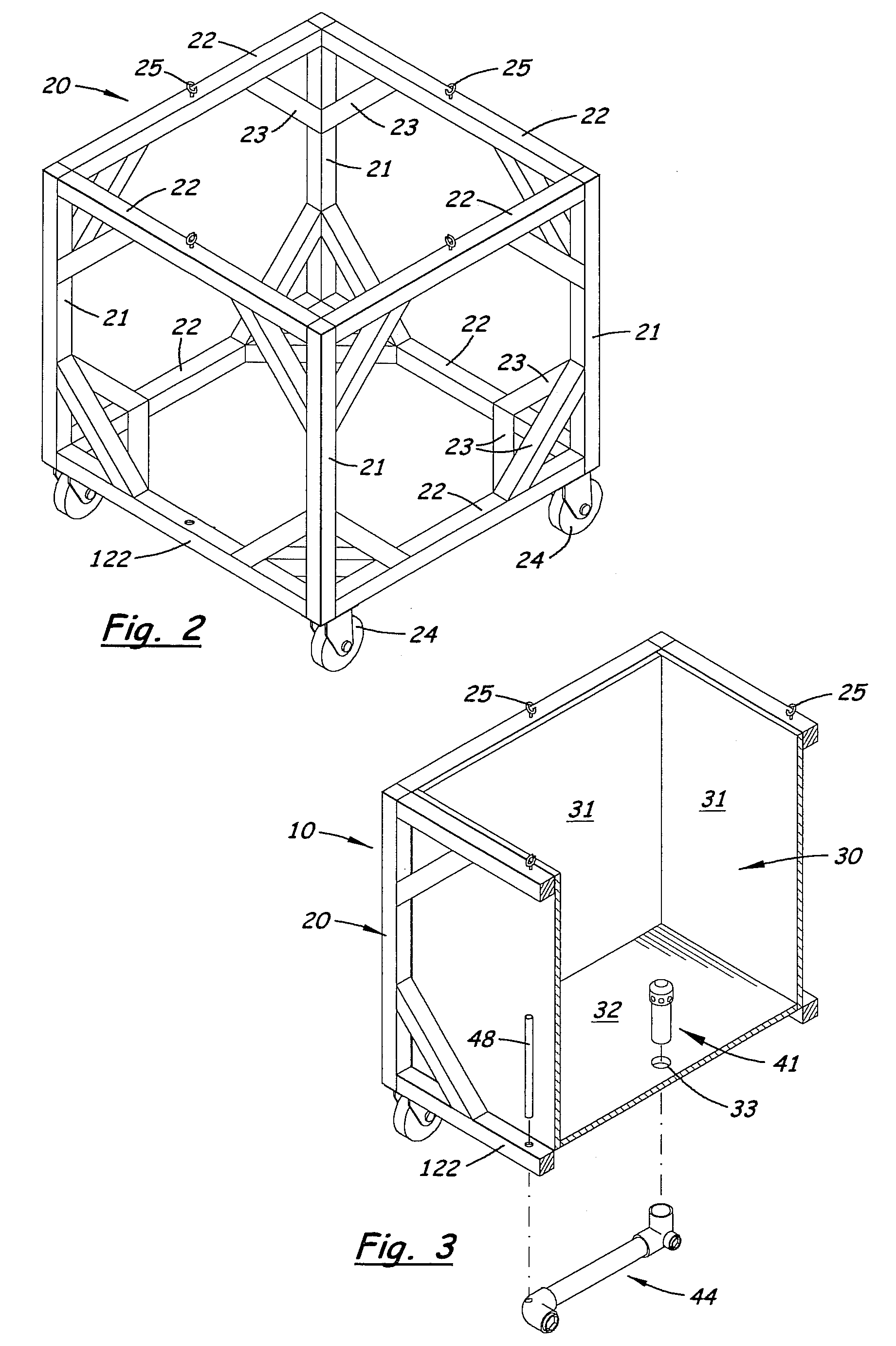
[0014]The preferred drainage system extends through a bottom wall of the container and to an outer sidewall of the container. The preferred drainage system is a generally U-shaped conduit, with a generally vertical inner portion inside the container, a generally horizontal portion extending underneath the container, and a generally vertical outer portion upending along the outer sidewall. The drainage system may be made substantially from easily-available commercial plumbing components and is small, light-weight and visually—inconspicuous compared to the large container.
[0015]The preferred generally vertical inner portion of the generally U-shaped conduit comprises a cap with a solid, non-perforated top surface, and a perforated vertical side surface. The non-perforated top surface blocks vertical, direct draining of water out of the container, while the perforated vertical side surface allows horizontal, indirect draining of water out of the container. Thus, the preferred cap tends to prevent soil loss.
[0019]The planter preferably comprises wheels for easy moving of the planter. This way, the planter may be rearranged on a patio or moved in and out of the sun, shade and / or cold, for example. The wheels lift the container-frame combination a distance above the patio surface to create a space that receives substantially all of the preferred drainage system.

Problems solved by technology

The drainage system may be made substantially from easily-available commercial plumbing components and is small, light-weight and visually—inconspicuous compared to the large container.

Method used


Image

  • Mobile planter
  • Mobile planter
  • Mobile planter

Examples


Embodiment Construction

[0027]Objects of the preferred embodiment include overcoming the typical deficiencies of both traditional planters and the complex alternative planters. The preferred embodiment provides a large container for soil and plants (hereafter, called a “plant container”), effective water drainage and soil retention, water level indication for excellent water table control, and efficient cleanout capability. In addition, all the aforementioned desirable characteristics are obtained with surprisingly simple, light-weight, and easy to operate and maintain apparatus.

[0028]A typical deficiency of the traditional planter is the water drain hole that allows water to drain directly out the bottom of the planter, thereby taking soil with it. “Directly” in this context means that the water drains substantially vertically down through the drain hole, with no structure between the soil and the drain hole to retain the soil in the planter. To avoid soil loss, the home remedy is to cover the drain hole ...


PUM


Abstract

A mobile gardening planter includes a plant container and a drainage system that is adapted for both dripless operation and drip-drain operation. The drainage system includes a drain cap inside the plant container that has holes preferably only in a vertical side of the drain cap for indirectly draining water out of the plant container into a drain pipe extending outside and across the bottom wall of the plant container. A generally vertically-extending sight tube fluidly communicates with the drain pipe so that the water level in the sight tube is the same as the water table level in the plant container, and the gardener may therefore monitor the water table. The open top end of the sight tube allows water to overflow the sight tube, to prevent undesirable over-watering. The sight tube is preferably shielded by a portion of the planter, and most preferably a portion of the frame, that extends outward from the plant container farther than does the sight tube. Openable cleanouts in the drainage system may be used to eliminate the water table or to flush and clean out the drain pipe assembly and / or the plant container. A plant support may be installed directly above the plant container for supporting the limbs and branches of the plant growing therein.

Description

[0001]This application claims priority of U.S. Provisional Application Ser. No. 60 / 944,857, filed Jun. 19, 2007, entitled “Mobile Planter,” the entire disclosure of which is hereby incorporated herein by this reference.BACKGROUND OF THE INVENTION[0002]1. Field of the Invention[0003]The present invention generally relates to plant husbandry and more specifically relates to planters used for container gardening.[0004]2. Related Art[0005]Gardeners who practice container gardening can choose from many traditional planters of various shapes, sizes, and aesthetic styles to accomplish their gardening goals. Traditional planters are basically containers for holding potting soil that have at least one water drain hole in the bottom surface of the container. Traditional planters usually come with deficiencies, which experienced gardeners frequently address by home remedies such as partially-blocking drain holes and / or adding water-catching trays, as will be discussed later in this document.[0...

Claims


Application Information

Patent Timeline
Patent Type & Authority Applications(United States)
IPC IPC(8): A01G25/00
CPCA01G9/02A01G9/12A01G27/008
Inventor NORVITCH, DANIEL A.
Owner NORVITCH DANIEL A
Learn More