Planer

a technology of power tools and planes, applied in the field of power tools, can solve problems such as difficulty in accessing certain surfaces to be planed

Active Publication Date: 2008-12-25
POWER BOX
View PDF16 Cites 3 Cited by
  • Summary
  • Abstract
  • Description
  • Claims
  • Application Information

AI Technical Summary

Benefits of technology

[0014]The provision of the two movement components allows the guard, when in the opened position, to have its external surface lie substantially flush with an adjacent external surface of the housing. The axial movement between the opened position and the intermediate position allows the guard to be moved clear of an external surface of the housing and then allows the same to be pivotally movable to the closed position.
[0015]When in the opened position, as the guard lies flush with the housing side wall, the guard does not provide any obstruction on the side wall to the use of the planer, and as a result the planer can be used to cut relativel...

Problems solved by technology

One known problem with planers is that access to certain surfaces which are to be planed can be difficult due to protrusions on the side walls of the planer clashing with parts of the workpiece.
This, in combination with the fact that the edges of the blades of the drum are offset from the edge of the plan...

Method used


Image

  • Planer
  • Planer
  • Planer

Examples


Embodiment Construction

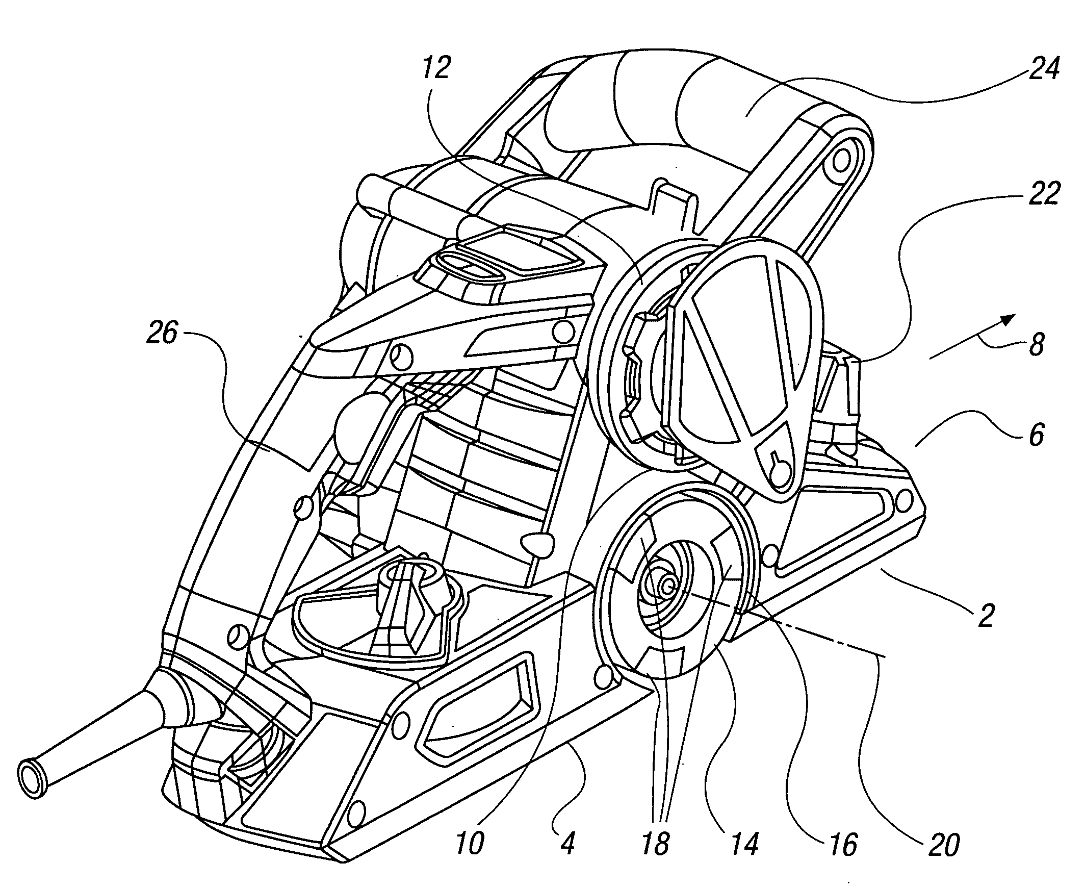
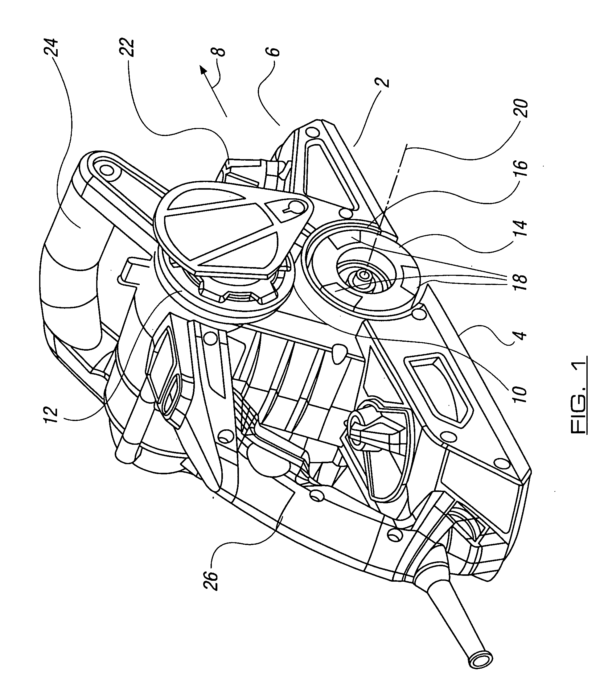
[0039]Referring first to FIG. 1, there is illustrated a planer power tool 2. The power tool incorporates a base 4 designed to pass along a workpiece surface (not shown) from which portions of material are removed using the tool. The tool has a front end 6 and is designed to be moved in a direction of arrow 8 along a workpiece. The power tool has a housing 10 in which is located a motor 12 connected to drive and rotate a drum 14 mounted in a chamber 16. The drum has a plurality of blades 18 at spaced intervals there around and is designed to be rotated about an axis 20 by the motor. The base position with respect to the drum can be selectively adjusted via adjustment means 22 by a user to control the depth from which the blades protrude below base 4 and, hence, select a depth of cut made on a workpiece. Dust and debris extraction means can be provided, and these will be described subsequently in more detail. A user grips the power tool via handles 24 and 26 to guide movement of the t...


PUM


Abstract

The invention provides a power tool planer which includes a drum with at least one blade thereon located within a chamber in the tool housing. One end of the chamber is provided with an opening which can be selectively closed by a guard. The guard can be moveable between a first closed position and a second position in which the chamber is opened, and the guard is moved into a recess in the housing to improve the ability to use the tool in confined spaces, as the guard lies flush with a side wall of the housing. Also provided is a dust and debris extraction system and a means for adjusting the depth of cut obtained using the tool.

Description

CROSS-REFERENCES TO RELATED APPLICATIONS[0001]This United States Application claims priority to British Patent Application No. 0710034.0 filed 25 May 2007.STATEMENT REGARDING FEDERALLY SPONSORED RESEARCH OR DEVELOPMENT[0002]Not ApplicableTHE NAMES OF THE PARTIES TO A JOINT RESEARCH AGREEMENT[0003]Not ApplicableINCORPORATION-BY-REFERENCE OF MATERIAL SUBMITTED ON A COMPACT DISC[0004]Not ApplicableBACKGROUND OF THE INVENTION[0005]The invention to which this application relates is a power tool in the form of a planer which can be used to remove portions of material from a workpiece surface along which the planer is moved.[0006]The planer includes a base surface which is used to contact the surface of the workpiece from which the material is to be removed. A drum is provided within the housing which is positioned adjacent to the base and the drum includes one or more blades mounted thereon. The drum protrudes a selectable distance from the base and the blades, as they rotate, cause remov...

Claims


Application Information

Patent Timeline
IPC IPC(8): B27C1/00
CPCB27C1/10B27G21/00
Inventor NICOLSON, MARCUS
Owner POWER BOX
Why Eureka
Try Eureka