Liquid sealing structure, manufacturing method of the same, liquid container, refilled liquid container, and refilling method of the same

a technology of liquid sealing and manufacturing method, which is applied in the direction of metal-working equipment, printing, writing implements, etc., can solve the problems of insufficient supply of ink to a sub-tank, inability to elastic seal the sealing member and the inner wall of the ink passage, and inability to meet the requirements of ink supply, etc., to achieve the effect of improving the commodity value and improving the commodity valu

Inactive Publication Date: 2008-12-25
SEIKO EPSON CORP
View PDF65 Cites 35 Cited by
  • Summary
  • Abstract
  • Description
  • Claims
  • Application Information

AI Technical Summary

Benefits of technology

[0046]With such a configuration, it is possible to re-use the recovered liquid container as the refilled liquid container just by further providing the coating film while re-using the sealing function of the torn sealing film before the recovery or the sealing film having the notch portion. In addition, it is possible to guarantee the commodity value of the recovered liquid container. Even when the liquid container has the torn sealing film, it is possible to improve the commodity value by covering the torn portion by use of the coating film. Even when the sealing film having the notch portion is mounted, the notch portion of the sealing film is deformed due to repeated use. Accordingly, it is possible to improve the commodity value by covering the torn portion by use of the coating film. When the recovered liquid container is used in the next time, in the liquid filling, the liquid filling member is inserted into the liquid passage through the notch portion of the coating film and the notch portion or the torn portion formed in the sealing film. In addition, upon leading out the liquid, the liquid lead-out member is inserted into the liquid passage through the notch portion of the coating film and the notch portion or the torn portion formed in the sealing film.

Problems solved by technology

However, when a flow amount of ink becomes increased to realize a high speed printing or a high precise printing of a printer, there arises a problem that ink cannot be sufficiently supplied to a sub-tank due to increase in a dynamic pressure of the ink supply tube.
However, if roundness of the ink passage of the ink lead-out portion deteriorates, for example, elastic sealing of the sealing member and the inner wall of the ink passage may be incomplete.
At this time, if elastic sealing of the sealing member and the inner wall of the ink passage is weak, the sealing may deteriorate due to the fed ink.
Moreover, if the ink cartridge falls or the ink cartridge is vibrated, the sealing between the sealing member and the inner wall of the ink passage may temporarily deteriorate.
Such problems are not limited to the ink cartridge, but may be generated in every apparatus in which an inner wall of a liquid passage formed in a liquid lead-out portion and a sealing member are elastically sealed.
However, resistance when the liquid lead-out member is inserted becomes reduced.

Method used


Image

  • Liquid sealing structure, manufacturing method of the same, liquid container, refilled liquid container, and refilling method of the same
  • Liquid sealing structure, manufacturing method of the same, liquid container, refilled liquid container, and refilling method of the same
  • Liquid sealing structure, manufacturing method of the same, liquid container, refilled liquid container, and refilling method of the same

Examples


first embodiment

[0068]Hereinafter, an embodiment of the invention will be described in detail. The following embodiment does not limit the invention described in Claims, but all the elements described according to the embodiment are not necessary as means for solving the problems of the invention.

Overall Configuration of Liquid Ejecting Apparatus

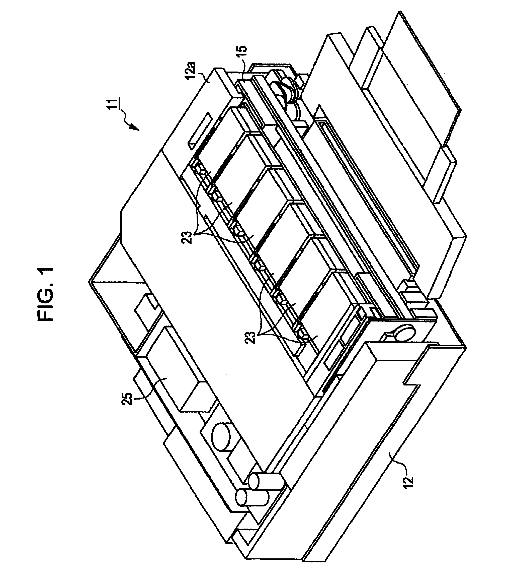
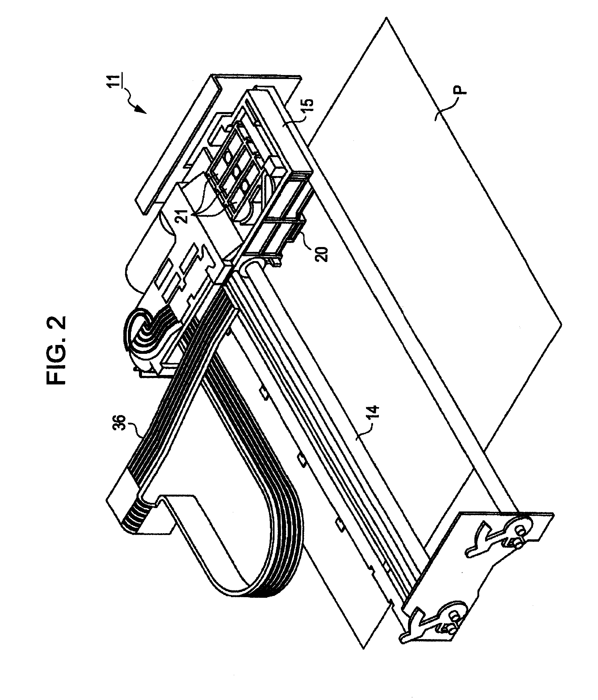
[0069]As shown in FIG. 1, as a liquid ejecting apparatus or a liquid consuming apparatus according to the embodiment, a printer 11 is covered with a frame 12. As shown in FIG. 2, a guide shaft 14, a carriage 15, a printing head 20 as a liquid ejecting head, valve units 21, ink cartridges 23 (see FIG. 1) as a liquid container, and a pressurizing pump 25 (see FIG. 1) are included in the frame 12.

[0070]As shown in FIG. 1, the frame 12 is a substantially rectangular box. A cartridge holder 12a is formed in the front surface of the frame 12.

[0071]As shown in FIG. 2, the guide shaft 14 is formed in a bar shape and is disposed in the frame 12. In the present embod...

second embodiment

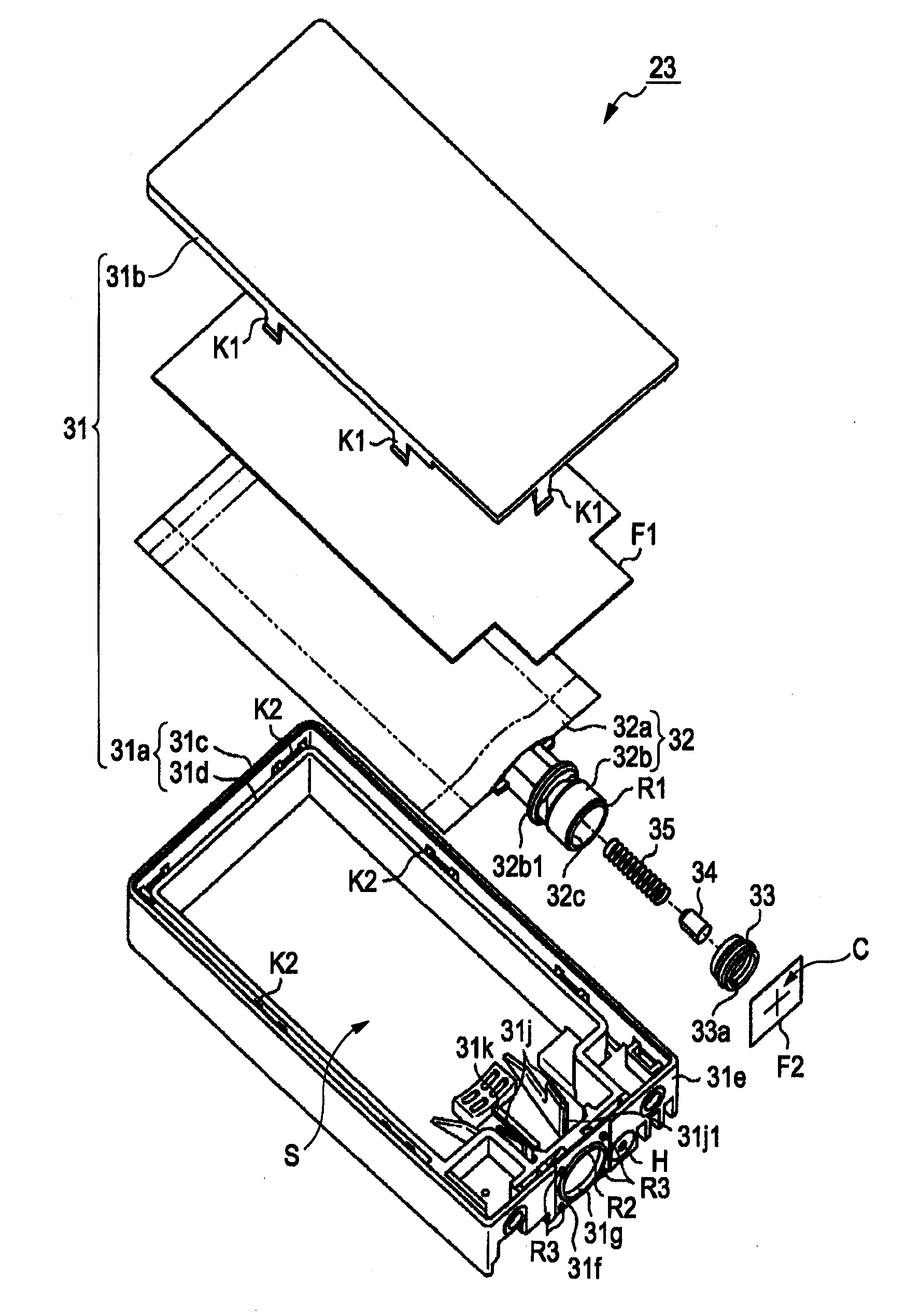
[0117]FIG. 6 is an exploded perspective view illustrating an ink lead-out portion 50 different from that according to the first embodiment. As shown in FIG. 6, the ink lead-out portion 50 has the outer shape different from that of the ink lead-out portion 32b according to the first embodiment. Moreover, in the present embodiment, the sealing film F2 having the notch portion C is not thermally welded to the ink case, but thermally welded only to an ink lead-out port 50 and a sealing member 60. Such a configuration according to the second embodiment is different from that according to the first embodiment, and the other configuration is the same as that according to the first embodiment. Moreover, a notch portion C shown in FIG. 6 may be a notch like the first embodiment as shown in FIG. 3.

[0118]FIG. 7 is a partial sectional view illustrating a case where the sealing member 60 is inserted into the ink lead-out port 51 and the sealing film F2 is not thermally welded.

[0119]The ink lead-...

third embodiment

[0123]A third embodiment will be described with reference to FIGS. 8 to 15B. A configuration of an ink cartridge as a liquid container according to the present embodiment is different from that according to the first embodiment. The ink cartridge according to the present invention can be mounted in the same liquid ejecting apparatus as that described in the first embodiment. Accordingly, a detailed description of the liquid ejecting apparatus is omitted.

[0124]FIG. 8 is an exploded perspective view illustrating the ink cartridge as the liquid container according to a third embodiment. FIG. 9A is a perspective view illustrating an ink pack as the liquid container and a spacer for filling gaps around the ink pack in a bag member receiving portion of the container body shown in FIG. 8. FIG. 9B is an enlarged view illustrating an IXB portion shown in FIG. 9A. FIG. 10 is an exploded perspective view illustrating a liquid level detecting unit shown in FIG. 8.

[0125]FIG. 11 is a perspective ...


PUM

PropertyMeasurementUnit
urging forceaaaaaaaaaa
sizeaaaaaaaaaa
dynamic pressureaaaaaaaaaa

Abstract

A liquid sealing structure includes: a liquid lead-out portion which has a liquid passage and an opening end surface formed in a liquid lead-out end of the liquid passage; a sealing member which is disposed on the opening end surface inside the liquid passage; a valve mechanism which is disposed inside the sealing member in the liquid passage to close the liquid passage; and a sealing film which covers the liquid passage and the opening end surface of the liquid lead-out portion and is thermally welded to the opening end surface and the sealing member, wherein a notch portion for passing a liquid lead-out member which is inserted into the liquid passage to open the valve mechanism is formed in the sealing film.

Description

BACKGROUND[0001]1. Technical Field[0002]The present invention relates to a liquid sealing structure suitable for an ink cartridge for a printer, a manufacturing method of the same, a liquid container, a refilled liquid container, and a refilling method of the same.[0003]2. Related Art[0004]In the past, an ink jet type printer as a liquid ejecting apparatus for ejecting liquid drops through a nozzle of a liquid ejecting head was known. The ink jet type printer has an off-carriage type ink supply system for mounting an ink cartridge on a portion other than a carriage. As a case where the ink jet type printer has the off-carriage type ink supply system, a case where a printer has a large-scale ink cartridge in order to print a large paper sheet and a case where an ink jet type printer is not mounted with an ink cartridge by reducing the size of the carriage to reduce the size of the ink jet type printer or make it thin.[0005]In the off-carriage type ink supply system, for example, the ...

Claims


Application Information

Patent Timeline
Patent Type & Authority Applications(United States)
IPC IPC(8): B41J2/175B41J29/393B21D53/76
CPCB41J2/17509B41J2/17513B41J2/1752B41J2/17553B41J2/17596B41J29/00Y10T29/49401
Inventor AOKI, YUJIKIMURA, HITOTOSHINOZAWA, IZUMI
Owner SEIKO EPSON CORP
Why Eureka
Try Eureka