
System and method for dynamic distributed communication

a distributed communication and dynamic technology, applied in data switching networks, time-division multiplexing selection, selective content distribution, etc., can solve the problems of increasing the number of users, limiting the ability of traditional communication systems to provide the necessary bandwidth and flexibility, and reducing the flexibility of traditional communication systems, so as to achieve rapid, scalable, and inexpensive growth of communication networks. , the effect of easy modification

Inactive Publication Date: 2008-12-25
QWEST
View PDF67 Cites 18 Cited by
  • Summary
  • Abstract
  • Description
  • Claims
  • Application Information

AI Technical Summary

Benefits of technology

"The present invention allows for automatic and dynamic addition of network routing elements to a distributed communication network. This allows for rapid, scalable, and inexpensive growth of the network, meeting customer needs, balancing resources, and satisfying physical constraints and government regulations. A new routing element can be added to the network by establishing a connection with an existing routing element and assigning an address to it. The assigned address can be from a pool of addresses maintained at the existing routing element. The network can support multiple types of information traffic and can be modified flexibly."

Problems solved by technology

However, difficulty remains in delivering this information to customers.
However, increases in the number of users, number and type of communication devices per user, and the information rate per device has strained the ability for traditional communication systems to provide the necessary bandwidth and flexibility.
While each technology has broadband delivery properties, each is subject to physical and signaling limitations that restrict availability in certain locations and for certain applications.
Further, each central office usually cannot support high-speed access for every customer within the central office coverage area.
Similarly, service provided by two-way cable modems is limited to the installation of coax, hybrid fiber coax and fiber-based systems by the cable provider as well as support capabilities of the supporting central office.
Currently, many premises do not have access to high-speed wireline voice, data, and video services due, in part, to the expense and difficulty in constructing or expanding central offices.
Several problems have developed with traditional wireless systems.
First, because all calls are processed by the central MSC, it can become a bottleneck limiting the number of users supported.
Second, if the MSC fails, the system becomes inoperative.
Third, the BSC and BTS architecture is fairly rigid, requiring manual reconfiguration in the MSC when components are added or deleted.
Fourth, circuit-switched channel connections establish an upper bandwidth, limiting communication rates.
Fifth, bandwidth is wasted if the communication rate does not reach the maximum established by the communication channel.
Sixth, high-speed data and video applications are impractical on wireless telecommunication systems designed primarily for voice.
However, because these systems typically operate at a high carrier frequency, receiving antennas must be positioned in line-of-sight with the transmitting antenna.

Method used


Image

  • System and method for dynamic distributed communication
  • System and method for dynamic distributed communication
  • System and method for dynamic distributed communication

Examples


Embodiment Construction

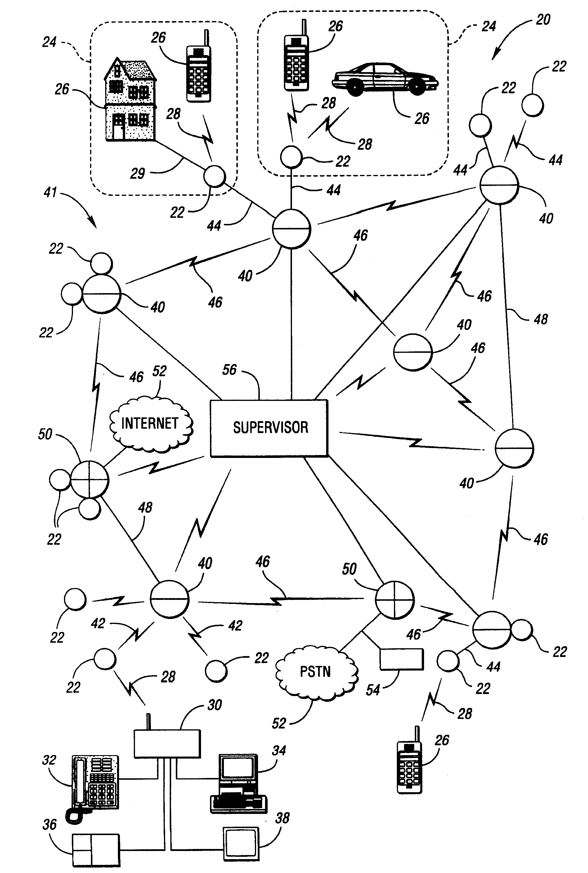
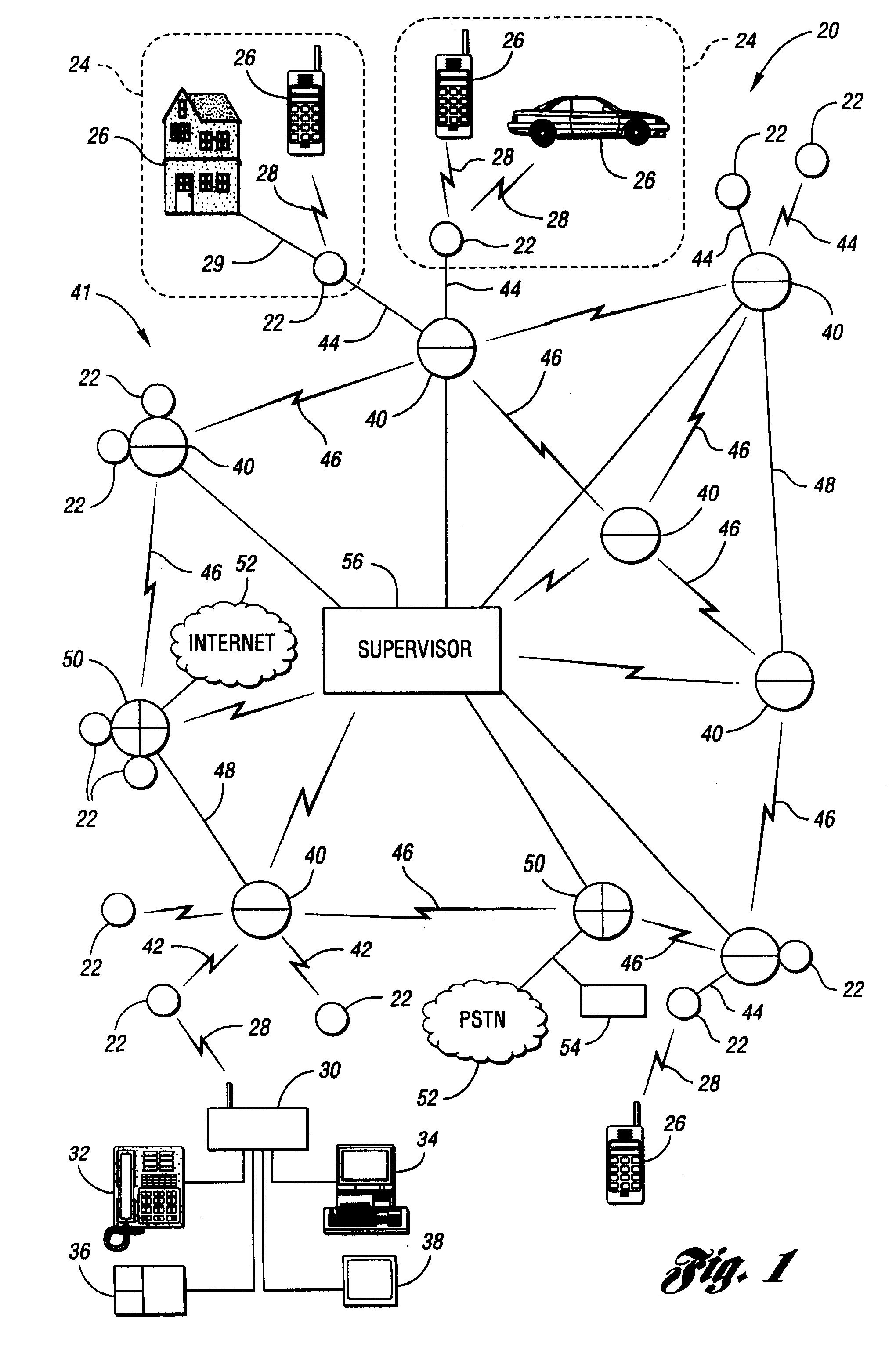
[0025]Referring to FIG. 1, a schematic drawing illustrating a portion of a communication system according to an embodiment of the present invention is shown. A communication system, shown generally by 20, includes a plurality of access points 22 which may be, for example, a local radio access point (LRAP). Each access point 22 defines coverage area 24 such as, for example, a cell, covering a reception range of access point 22. Coverage area 24 may be formed from many independent sectors, as may result if access point 22 uses many unidirectional antennas, or may be a single region resulting from the use of an omnidirectional antenna. Subscriber unit 26 within coverage area 24 may establish two-way wireless link 28 with access point 22. Subscriber unit 26 may also establish wireline link 29 with access point 22. Links 28, 29 may be symmetrical or asymmetrical. Subscriber unit 26 may be fixed or non-fixed and, if non-fixed, may posses varying degrees of portability and mobility. Subscr...


PUM


Abstract

Growth of a distributed communication system is facilitated through dynamic addition of routing elements. A new routing element may be added to a network of routing elements by first establishing a connection between the new routing element and an existing routing element in the network. The connection may be either wireless or wireline. At least one address is assigned to the new routing element. Each assigned address comes from a pool of addresses maintained at the existing routing element. At least one pool of addresses is issued to the new routing element, permitting the new routing element to dynamically add yet another new routing element to the network of routing elements.

Description

CROSS-REFERENCE TO RELATED APPLICATIONS[0001]This application is a continuation of application Ser. No. 10 / 847,787, filed May 18, 2004, which is a divisional of application Ser. No. 09 / 603,035, filed Jun. 23, 2000, which claims the benefit of U.S. Provisional Application No. 60 / 152,730, filed Sep. 8, 1999 and U.S. Provisional Application No. 60 / 185,788, filed Feb. 29, 2000. The specification of each of Application Nos. 60 / 152,730 and 60 / 185,788 is expressly incorporated herein by reference in its entirety.TECHNICAL FIELD[0002]The present invention relates to dynamically modifying communication network components.BACKGROUND ART[0003]Communication systems are increasingly being required to provide a wide range of services, including different forms of information communicated and different communication characteristics. Information forms include voice, data, video, telemetry, and the like. Communication characteristics include quality, complexity, latency, reliability, cost, availabil...

Claims


Application Information

Patent Timeline
Patent Type & Authority Applications(United States)
IPC IPC(8): H04L12/56H01Q1/06H01Q1/12H04L12/28H04L12/46H04L12/64H04L29/06H04L29/12H04Q11/04H04W4/18H04W8/26H04W40/02H04W80/04H04W88/08
CPCH01Q1/06H01Q1/1242H04L12/4608H04L12/6402H04L29/06H04L29/12018H04L29/12216H04L29/12283H04L29/12301H04L29/12311H04L61/10H04L61/2007H04L61/2061H04L61/2076H04L61/2084H04L2012/5607H04L2012/561H04L2012/5618H04L2012/5671H04N21/6131H04Q11/0478H04W4/18H04W8/26H04W40/02H04W80/04H04W88/08H04W88/085H04L69/08H04L61/5007H04L61/5061H04L61/5076H04L61/5084H04L9/40
Inventor DOUGHERTY, ANGUS O.HOHNSTEIN, DONALD L.COOK, CHARLES I.WELLS, GUY M.
Owner QWEST
Learn More