Method and System for Filtering Elongated Features

a technology of feature and filtering method, applied in image enhancement, instruments, computing, etc., can solve the problems of high computational cost of neither the design of a steerable filter kernel nor the linear combination, and achieve the effect of more efficien

Inactive Publication Date: 2008-12-25
KONINKLIJKE PHILIPS ELECTRONICS NV
View PDF2 Cites 8 Cited by
  • Summary
  • Abstract
  • Description
  • Claims
  • Application Information

AI Technical Summary

Benefits of technology

[0010]An object of the invention is to provide a solution for filtering elongated features, which is more efficient.

Problems solved by technology

Moreover, neither the design of a steerable filter kernel nor the linear combination involve high computational costs.

Method used


Image

  • Method and System for Filtering Elongated Features
  • Method and System for Filtering Elongated Features
  • Method and System for Filtering Elongated Features

Examples


second embodiment

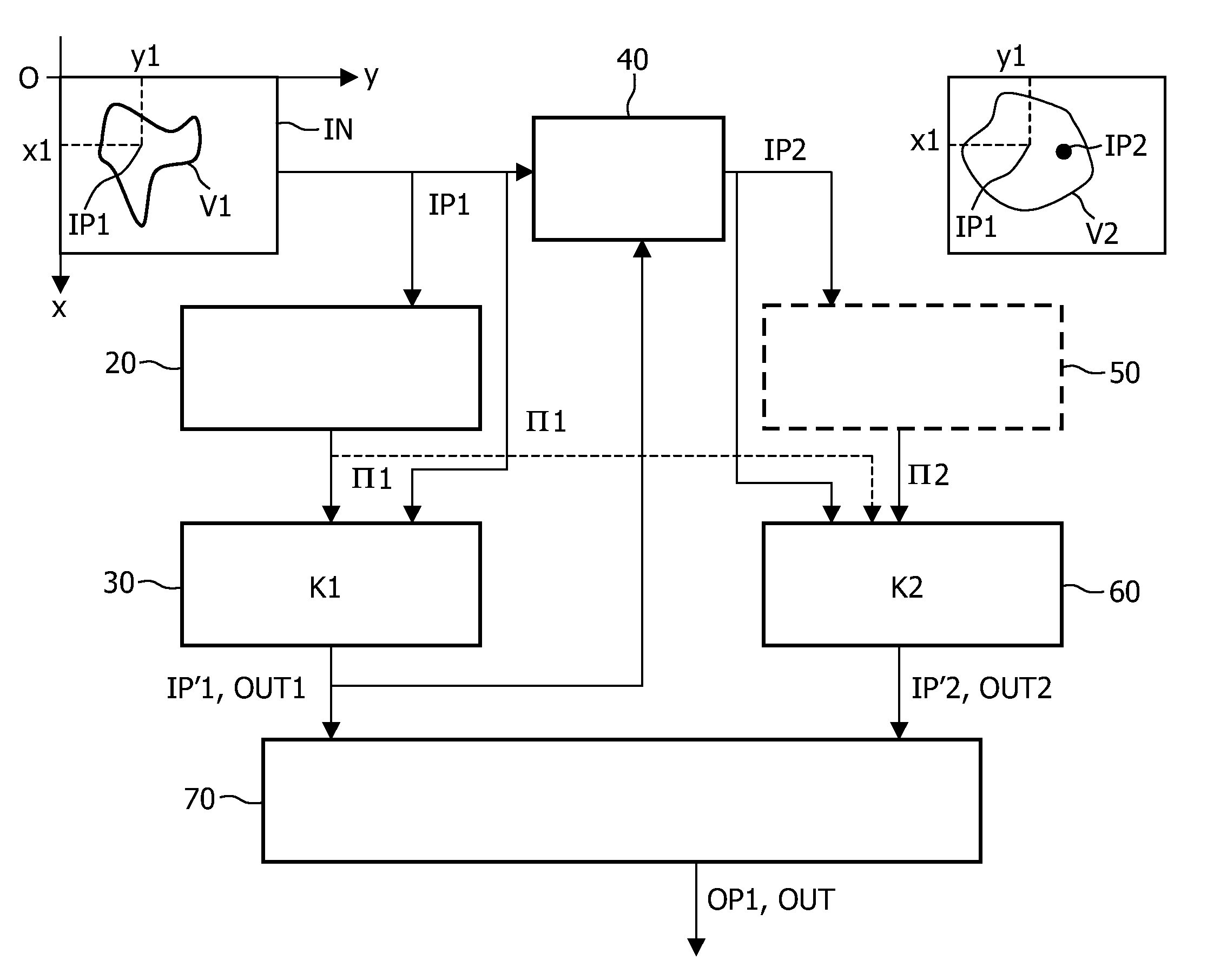
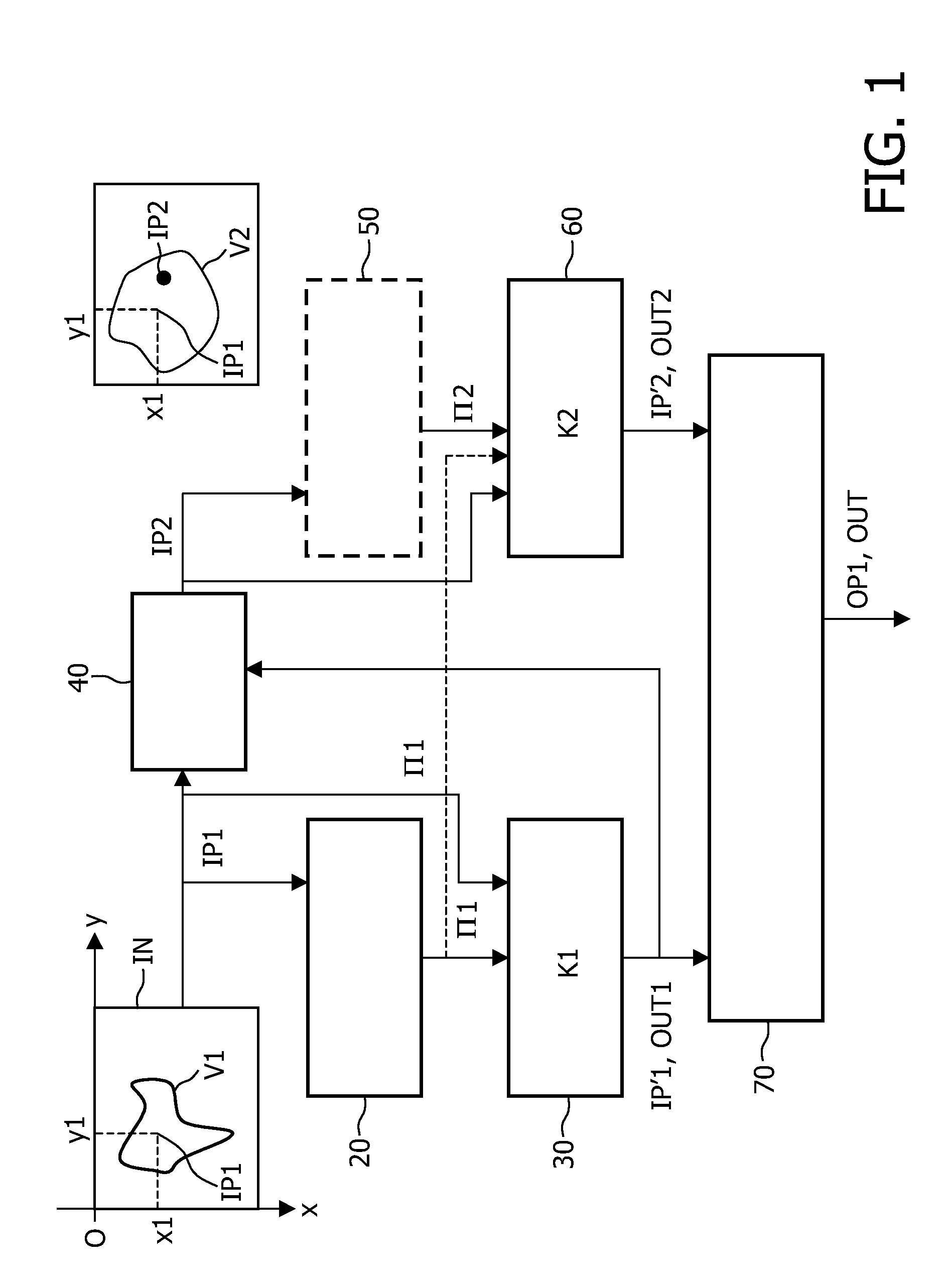
[0057]Referring to FIG. 4B and in accordance with the invention, the method further comprises a step analysing intensity levels of the input image in a second vicinity V2 of the second image point for calculating the second direction of filtering θ2 at said second image point IP2. As already mentioned above, this analysis is performed by using known image processing techniques, for instance by applying a gradient operator to the input image.

[0058]Therefore, the contribution of the second steerable filter kernel K2 to the linear combination has the effect of extending the first steerable filter kernel K1 in the direction of a curved feature CF present in the image at the second image point. A consequence is that a curved elongated filter K is designed, which fits better with the local intensity of the image and brings improved feature enhancement results on elongated curved features CF.

[0059]Referring to FIG. 4C and in accordance with a third embodiment of the invention, the step of ...

fourth embodiment

[0062]Referring to FIG. 5B and in accordance with the invention the second and third output image points IP2, IP3 are located on a curve C comprising the first output image point IP1. Such a curve is either a circle, which is defined by a curvature radius or a parabolic curve or any kind of curve, which is defined on the basis of analysis parameters calculated on the image such as the curvature of the elongated features. Advantageously, the curve has a shape which is related to the elongated features present in the image. Therefore, the defined curve can be used as a guide for designing of a curved elongated filter K which fits better with complex elongated structures of the input image.

[0063]Preferably, the third image point IP3 is selected in such a way that said third image point IP3 is symmetric on the curve C to the second image point IP2 with respect to the first image point. An advantage is that the elongation of the first steerable kernel is the same on both sides of the fir...


PUM


Abstract

The present invention relates to a method of filtering an input image for producing an output image. The method comprising the steps of, for a first image point located at first spatial coordinates:—analysing intensity levels of the input image in a first vicinity of the first image point for calculating a first direction of filtering at said first image point;—computing an intensity level of a first output image point of a first output image by applying a first steerable filter kernel to the input image, which is centered at the first image point and oriented along the calculated first direction of filtering; selecting at least a second image point in a second vicinity of said first image point in the first output image;—computing an intensity level of at least one second output image point of a second output image by applying at least a second steerable filter kernel to the input image, which is centered at the at least second image point and oriented along a second direction of filtering;—calculating a linear combination of the first output image point and of the at least second output image point for providing an output intensity level;—applying said output intensity level to an output image point of said output image, said output image point having said first spatial coordinates.

Description

FIELD OF THE INVENTION[0001]The present invention relates to a method of filtering an input image using elongated filters. The present invention also relates to a system for filtering an input image, said system implementing said method. The present invention finally relates to a computer program for carrying out said method.[0002]The present invention finds its application in the general domain of image processing for enhancing elongated features and, in particular, in the domain of medical image processing for detecting a guide wire introduced in the body of a patient.BACKGROUND OF THE INVENTION[0003]In medical image processing, it is often needed to enhance elongated features such as blood vessels, ribs or catheters. To this end, several techniques have been developed for designing oriented filters.[0004]Document entitled “The Design and Use of Steerable Filters” by W. Freeman and E. Adelson, published in IEEE Transactions on Pattern Analysis and Machine Intelligence, Vol. 13 (9)...

Claims


Application Information

Patent Timeline
Patent Type & Authority Applications(United States)
IPC IPC(8): G06K9/40
CPCG06K9/4619G06K2209/057G06T5/20G06V10/449G06V2201/034
Inventor FLORENT, RAOULSAMSON, CHRISTOPHE
Owner KONINKLIJKE PHILIPS ELECTRONICS NV
Why Eureka
Try Eureka