Vehicle power storage unit and vehicle

a technology for power storage units and vehicles, applied in the direction of electrochemical generators, electric devices, cell components, etc., can solve the problems of increased weight, increased weight, and increased weight of power storage units, and achieve the effect of increasing internal pressur

Inactive Publication Date: 2008-12-25
TOYOTA JIDOSHA KK
View PDF0 Cites 57 Cited by
  • Summary
  • Abstract
  • Description
  • Claims
  • Application Information

AI Technical Summary

Benefits of technology

[0013]The invention provides a power storage unit that is simply structured to suppress an increase in the internal pressure of the power storage unit due to the gas produced by a power storage assembly.

Problems solved by technology

However, if the thickness of the container is increased to increase its compressive strength, its weight increases accordingly, making the power storage unit larger in size and heavier in weight.
However, if the internal pressure of the container increases sharply due to the gas produced by the respected battery cells, the gas may not be discharged sufficiently through the gas-discharge pipe only.
Therefore, the power storage unit needs to be made large in size and heavy in weight.
In this case, however, the manufacturing procedure of the lid becomes complicated and the production cost increases accordingly.

Method used


Image

  • Vehicle power storage unit and vehicle
  • Vehicle power storage unit and vehicle
  • Vehicle power storage unit and vehicle

Examples


Embodiment Construction

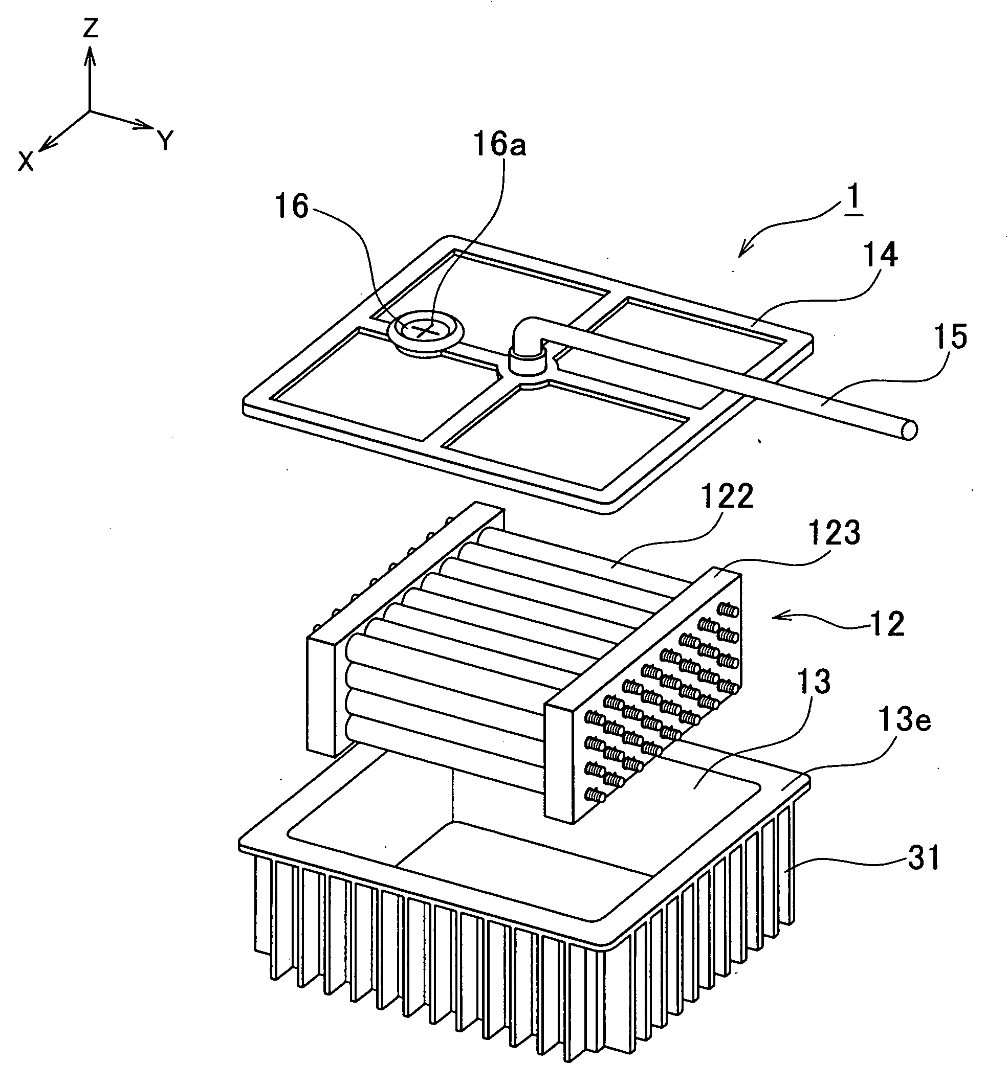
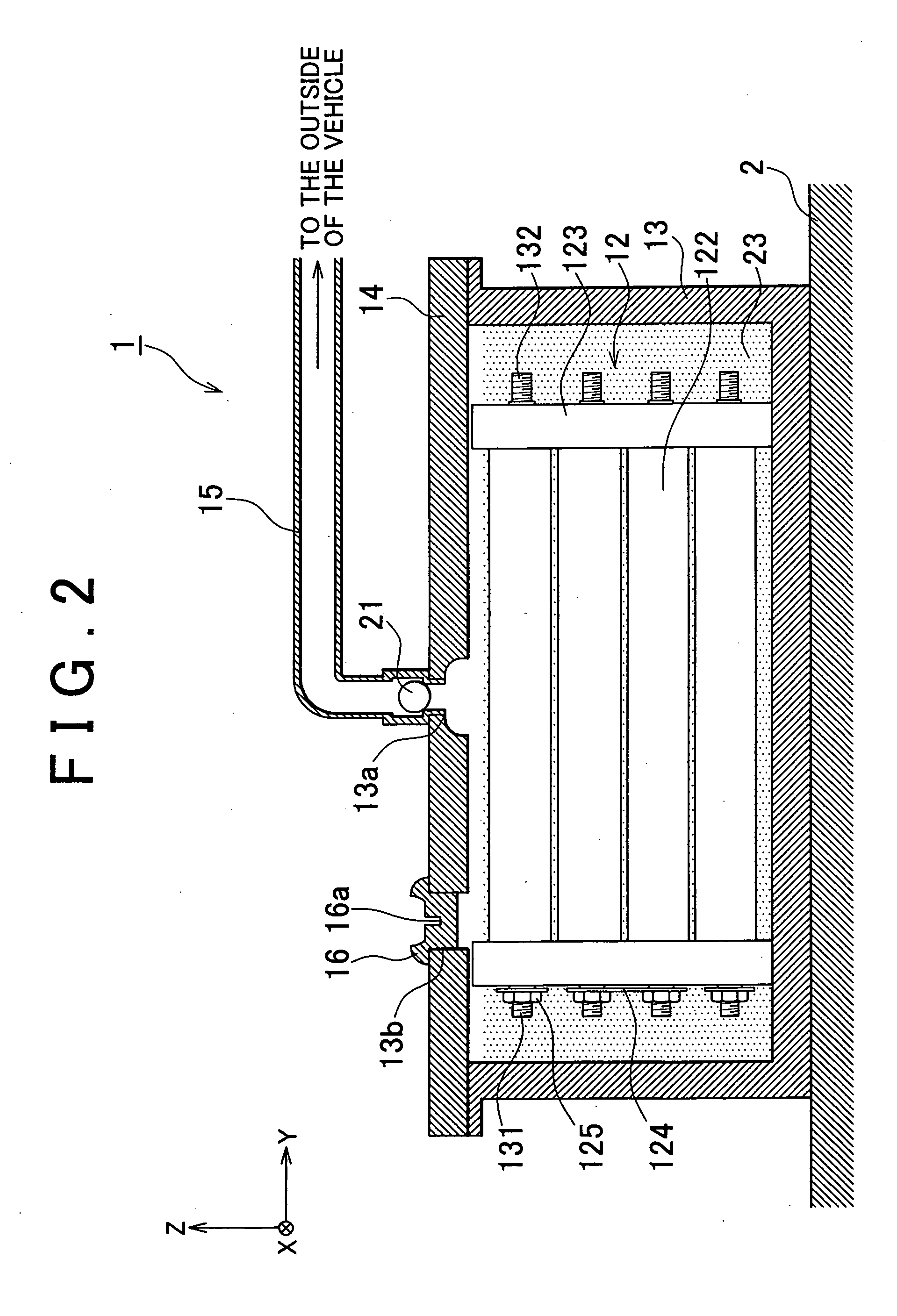
[0026]FIG. 1 is an exploded perspective view of a power storage unit 1 according to the first example embodiment of the invention, and FIG. 2 is a cross-sectional view of the power storage unit 1. Referring to FIG. 1 and FIG. 2, the power storage unit 1 has a battery assembly 12 constituted of a plurality of cylindrical batteries 122 electrically connected to each other (“power storage assembly”), a battery case (“casing”) 13 containing the battery assembly 12 and coolant 23, and a case cover (“casing”) 14 serving as a lid of the battery case 13. The power storage unit 1 is used as a drive power source or an auxiliary power source for hybrid vehicles and electric vehicles. The power storage unit 1 is mounted on a floor panel 2 beneath the navigator seat in a vehicle.

[0027]The outline of the power storage unit 1 is as follows. A gas-discharge pipe (“gas-discharge pipe”) 15 is connected to the immediate vicinity of the center of the battery case 13, and a gas-relief valve (“second pre...


PUM

PropertyMeasurementUnit
pressureaaaaaaaaaa
pressureaaaaaaaaaa
valve-open pressureaaaaaaaaaa

Abstract

A vehicle power storage unit, has: a power storage assembly; a coolant for cooling the power storage assembly; a casing having a coolant inlet through which the coolant is filled into the casing and containing the coolant and the power storage assembly; a gas-discharge pipe through which gas produced by the power storage assembly is discharged from the casing to the outside of a passenger compartment or a trunk of the vehicle; and a first pressure-release valve which is provided at the coolant inlet and through which the pressure in the casing is released to the outside when gas is produced by the power storage assembly.

Description

INCORPORATION BY REFERENCE[0001]The disclosure of Japanese Patent Application No. 2007-163117 filed on Jun. 20, 2007 including the specification, drawings and abstract is incorporated herein by reference in its entirety.BACKGROUND OF THE INVENTION[0002]1. Field of the Invention[0003]The invention relates to a vehicle power storage unit constituted of a power storage assembly and a casing containing the power storage unit and coolant for cooling said unit. The invention also relates to and a vehicle incorporating said unit.[0004]2. Description of the Related Art[0005]In recent years, various motor-driven vehicles such as electric vehicles and hybrid vehicles have been widely developed, and there have been increasing demands for secondary batteries providing a high performance, a high reliability, and a high sedulity, as drive power sources or auxiliary power sources for such motor-driven vehicles.[0006]Power sources used as the power source for propelling a motor-driven vehicle or as...

Claims


Application Information

Patent Timeline
Patent Type & Authority Applications(United States)
IPC IPC(8): B60K11/00B60K1/04B60K11/02B60L3/00H01M10/60H01M10/613H01M10/625H01M10/643H01M10/6551H01M10/6567H01M50/213
CPCH01M2/1072H01M2/1229H01M2/1241H01M10/625H01M10/6551H01M10/6567H01M10/643H01M10/613Y02E60/10H01M50/325H01M50/3425H01M50/213
Inventor TAKAGI, MASARU
Owner TOYOTA JIDOSHA KK
Why Eureka
Try Eureka