Method and Apparatus for Inserting a Catheter Device

Inactive Publication Date: 2008-12-25
AMISAR SHAI +1
View PDF18 Cites 104 Cited by
  • Summary
  • Abstract
  • Description
  • Claims
  • Application Information

AI Technical Summary

Benefits of technology

[0026]In one preferred embodiment of the aforementioned catheter insertion system, the advancing means comprises the sealed catheter sleeve and a plurality of blades situated in close proximity to the distal end of said sleeve, such that when said sleeve is grasped and advanced in a distal direction, the catheter situated within said sleeve is similarly advanced, and said sleeve is progressively cut by said blades, thereby facilitating its removal from said system.
[0040]The slender passage element may be a part of a splittable head sealably fitted into the distal end of the flexible sleeve, wherein the splittable head is constructed such that it can be longitudinally split into two or more parts, thereby facilitating tearing of the flexible sleeve. Additionally, the splittable head may comprise pins adapted to be engaged in respective apertures provided in the flexible sleeve. The splittable head may further comprise splitting tabs provided on each splittable part thereof.

Problems solved by technology

A considerable disadvantage of the prior art catheter devices stems from the requirement to insert the full length of the catheter tube into the artery site for performing continuous in vivo procedures.
It is difficult to estimate the length of the catheter tube required for carrying out a specific procedure.
None of the aforementioned publications provides means for controlling the insertion of the catheter.
The prior art devices do not include control means for controlling the insertion of the catheter tube.
In addition, the prior art catheter devices do not provide means for preventing accidental withdrawal, or means for preventing the use of excess force that may result in internal injuries.
Moreover, the prior art devices do not provide means for carrying out the requisite procedure with a partially inserted catheter.

Method used


Image

  • Method and Apparatus for Inserting a Catheter Device
  • Method and Apparatus for Inserting a Catheter Device
  • Method and Apparatus for Inserting a Catheter Device

Examples


Embodiment Construction

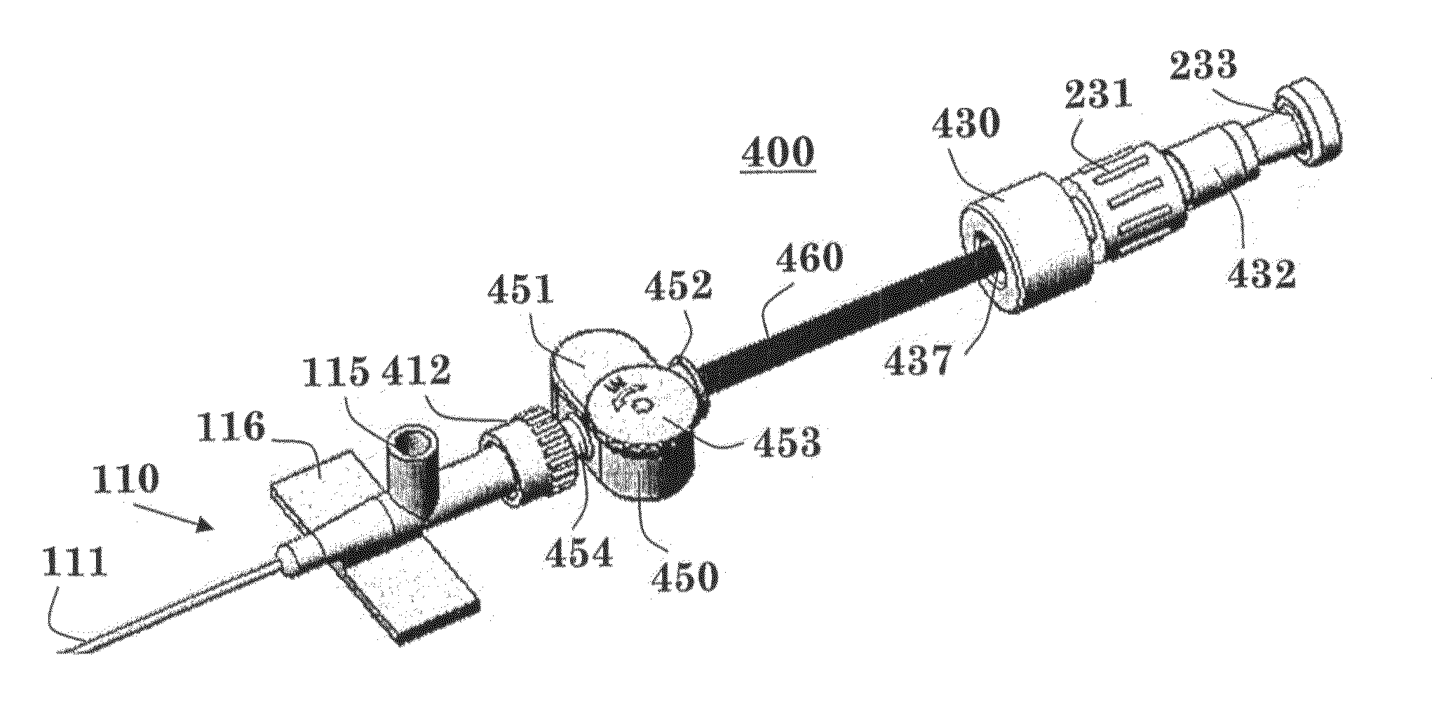
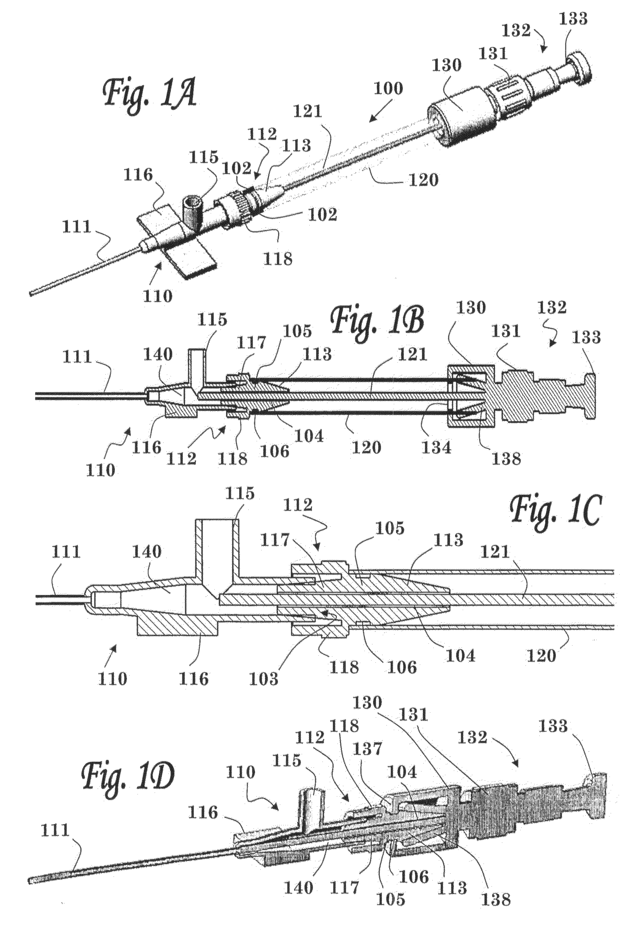
[0101]FIG. 1A shows a perspective view of a catheter insertion device of the present invention (before insertion of the catheter tube into the blood vessel). In this preferred embodiment the intravascular catheter insertion device 100 comprises three main elements: entry port 110 (bearing an insertion cannula 111 at its distal-most end), proximal hub 132 and sealing sleeve 120, said sleeve 120 being located between said entry port 110 and said proximal hub 132. Sealing sleeve 120 is sealably connected at its proximal end to the inner bore of proximal hub 132, and sealably connected at its distal end to entry port 110, as will be described in more detail hereinbelow.

[0102]Before use, the device is preferably provided in two sections: (i) a distal section comprising the entry port 110 (having a disposable needle inserted within its central bore), and (ii) a proximal section comprising proximal hub 132 connected to sealing sleeve 120.

[0103]Following placement of the insertion cannula 1...


PUM


Abstract

The present invention relates to systems and methods for inserting a catheter device into a subject, wherein the catheter insertion system generally comprises a flexible sleeve containing a catheter tube and advancing means for advancing the catheter contained within said system in a distal direction, wherein the flexible sleeve has a sealed proximal end and a distal end which may comprise a slender passage adapted to allow passage of said catheter tube therethrough while preventing backflow of fluid into the flexible sleeve.

Description

FIELD OF THE INVENTION[0001]The present invention relates to intravascular catheter devices. More particularly, the invention relates to methods and apparatuses for facilitating and controlling the insertion of a catheter device.BACKGROUND OF THE INVENTION[0002]It is known in the art to provide peripheral intravenous therapy using a catheter having a cannula or catheter tube to provide access into subcutaneous veins thereby to introduce medication, drugs, chemotherapy, nutrition and various other fluids into a vein of a subject. The present procedure includes inserting a hypodermic needle together with a catheter having an in-dwelling cannula into a suitable vein, withdrawing the needle and leaving the in-dwelling cannula in the vein. Such a catheter is typically provided with a suitable closure and various adapter mechanisms to enable the aseptic introduction of fluid medicaments from a hypodermic syringe or from an intravenous drip.[0003]U.S. Pat. No. 5,478,326 describe an arteria...

Claims


Application Information

Patent Timeline
IPC IPC(8): A61M25/092A61M25/09A61M25/18
CPCA61M25/0111A61M25/0113A61M25/0606A61M25/0662A61M25/0668A61M25/09041A61M2025/0675A61M2025/0681
Inventor AMISAR, SHAIRADOMSKI, RONEN
Owner AMISAR SHAI
Why Eureka
Try Eureka