Device delivery system with balloon-relative sheath positioning

a technology of relative sheath positioning and delivery system, which is applied in the field of delivery system and delivery method for the deployment of medical devices, can solve the problems of system straightening, inaccurate positioning, and perforation of the vessel wall, and achieve the effect of facilitating balloon inflation

Inactive Publication Date: 2008-12-25
CAPELLA
View PDF25 Cites 28 Cited by
  • Summary
  • Abstract
  • Description
  • Claims
  • Application Information

AI Technical Summary

Benefits of technology

[0024]In yet another embodiment a method of providing an ostial protection device delivery system comprises: providing a catheter having a distal end and a proximal end; positioning a deflated balloon at the distal end of the catheter, the balloon comprising wing portions; wrapping the wing portions about the distal portion of the catheter so as to facilitate inflation of the balloon; providing an ostial protection device about the deflated balloon; positioning an elongate tubular sheath, the sheath having a proximal end and a distal end oriented with the catheter, the sheath comprising a predefined sheath portion, about the ostial protection device and the balloon to hold the ostial protection device in a compressed state; and orienting the predefined sheath portion in a predetermined relationship as a function of locations of the folded wing portions of the balloon.

Problems solved by technology

There have been, however, problems associated with these delivery systems.
This movement can lead to inaccurate positioning and, in some instances, possible perforation of the vessel wall by a protruding end of the prosthesis.
As the wire is actuated, tension in the delivery system can cause the system to straighten.
This change of the geometry of the system within the anatomy can also lead to inaccurate prosthesis positioning.
While the perforations may help to control the rupturing of the sheath by providing a “weak” portion, the dynamics of sheath rupturing are still not well controlled.

Method used


Image

  • Device delivery system with balloon-relative sheath positioning
  • Device delivery system with balloon-relative sheath positioning
  • Device delivery system with balloon-relative sheath positioning

Examples


Embodiment Construction

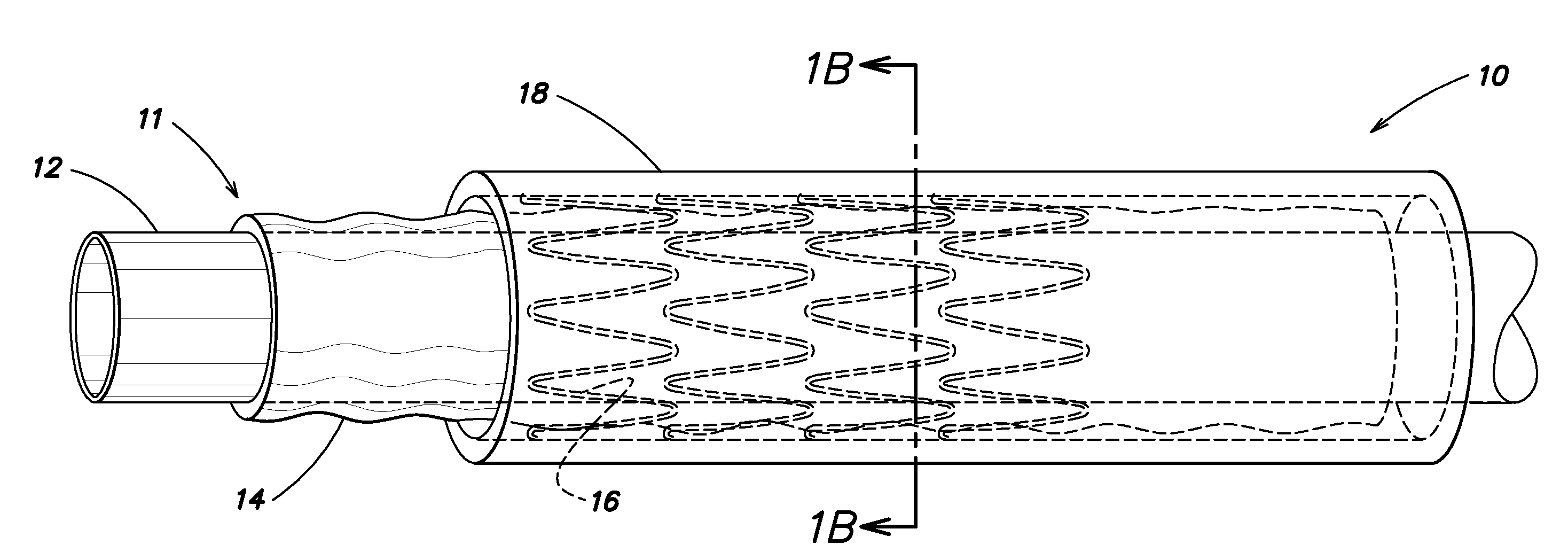
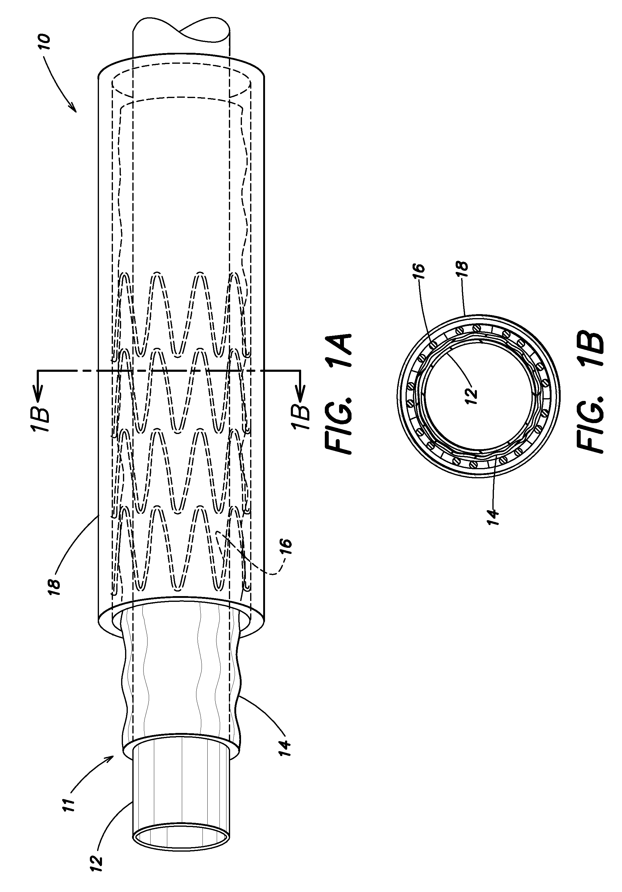
[0039]A medical device delivery system, as shown in FIG. 1A, includes a delivery catheter 12 with a balloon 14 positioned at, or enclosing, a distal end 11 of the catheter 12. As is known, a lumen is provided to inflate the balloon 14 as necessary during the procedure to deliver a device 16, for example, a stent, that is placed at the distal end of the catheter 12 and around the balloon 14. As per the present discussion, the device 16 is a self expanding device and, therefore, a sheath 18 is also disposed at the distal end 11 of the catheter 12 so as to enclose the device 16 and the balloon 14. The sheath 18 is attached to the catheter 12 at some point proximal to the distal end 11 of the catheter 12.

[0040]A cross section of the system 10, along line 1B-1B, is presented in FIG. 1B. As shown, the sheath 18 surrounds the stent or device 16 and the balloon 14 positioned on the catheter 12.

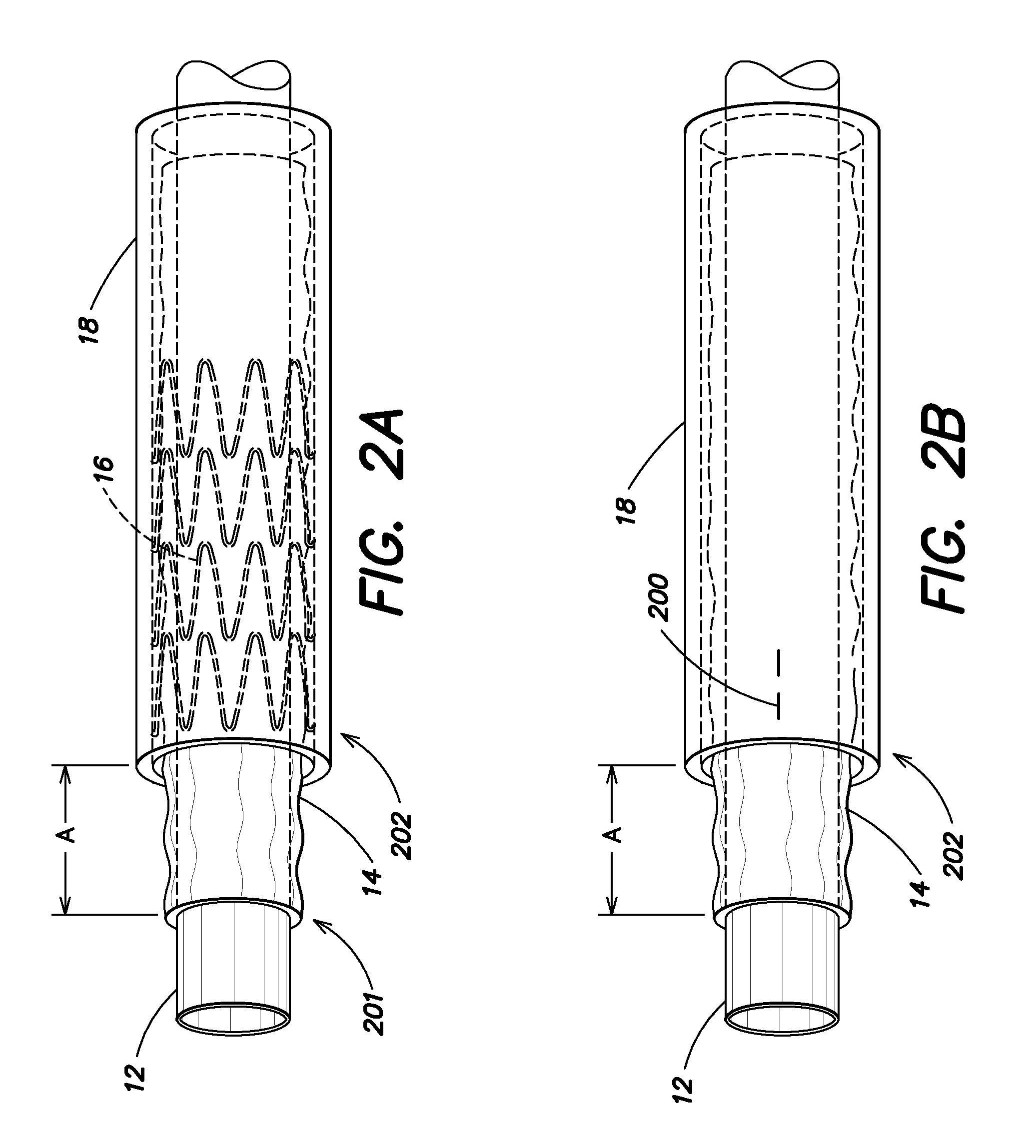
[0041]Referring to FIG. 2A, a simpler representation of the system 10 of FIG. 1A, is shown where a...


PUM


Abstract

A medical device delivery system includes a self-expanding medical device mounted on a balloon portion of a catheter. A sheath is provided around the medical device to hold the device in place with the device staying in a compressed state. A series of perforations or an initial cut is provided in the sheath at a predetermined location, or within a predetermined range of locations, on the circumference of the sheath. The predetermined location or range of locations are determined with respect to the folds of the balloon portion.

Description

RELATED APPLICATIONS[0001]1. Field of the Invention[0002]The present invention relates to a delivery system and method for deployment of a medical device, e.g., a self-expanding vascular device, in the vasculature of a patient. More particularly, a delivery system having a sheath with portions specifically positioned relative to a balloon positioned therein is described.[0003]2. Background of the Invention[0004]As is known, treatment of vascular blockages due to any one of a number of conditions, such as arteriosclerosis, often comprises balloon dilatation and treatment of the inner vessel wall by placement of a stent. These stents are positioned to prevent restenosis of the vessel walls after the dilatation. Other devices, often referred to as drug eluting stents, are now being used to deliver medicine to the vessel wall to also help reduce the occurrence of restenosis.[0005]These stents, i.e., tubular prostheses, typically fall into two general categories of construction. The firs...

Claims


Application Information

Patent Timeline
Patent Type & Authority Applications(United States)
IPC IPC(8): A61M25/10A61F2/958
CPCA61F2/958A61F2/97A61M2025/1004
Inventor SLATTERY, DAVIDKELLY, DAMIANGILMORE, MICHAELSTECKEL, MARK
Owner CAPELLA
Why Eureka
Try Eureka