
Systems and Methods For Measuring Multiphase Flow in a Hydrocarbon Transporting Pipeline

a technology of multi-phase flow and hydrocarbon transport, which is applied in the direction of liquid/fluent solid measurement, instruments, specific gravity measurement, etc., can solve the problems of oil and water being partially or even completely separated, difficult to obtain high-accuracy flow rate measurements, and difficulty in obtaining flow measurements of different phases

Active Publication Date: 2008-12-25
SCHLUMBERGER TECH CORP
View PDF25 Cites 95 Cited by
  • Summary
  • Abstract
  • Description
  • Claims
  • Application Information

AI Technical Summary

Benefits of technology

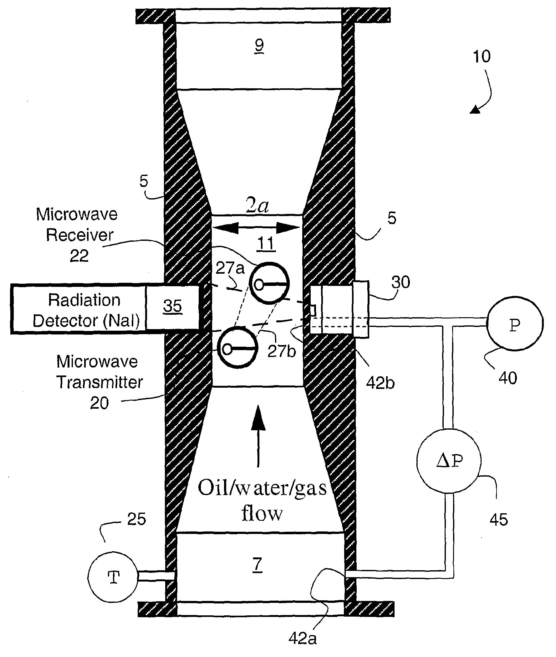
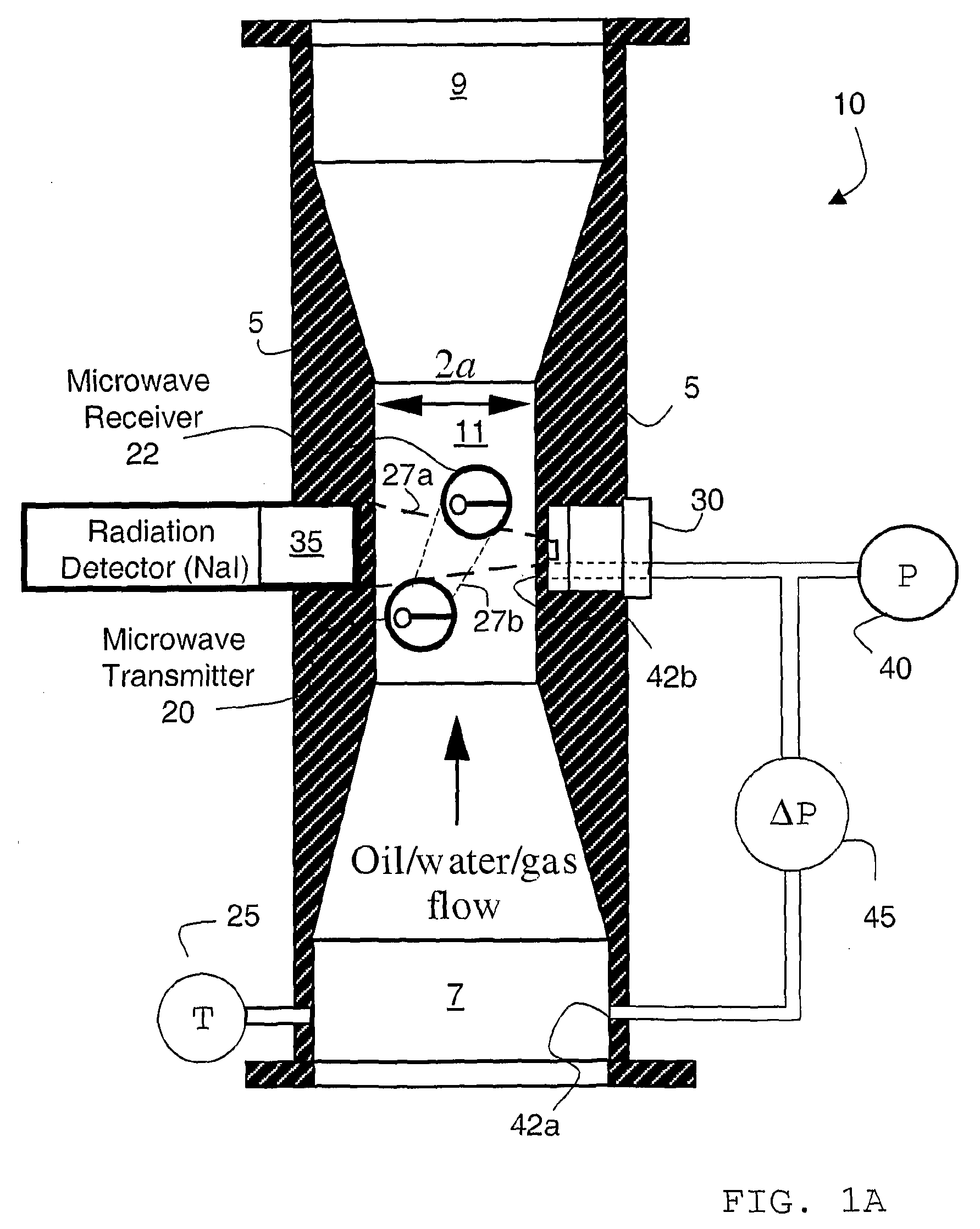
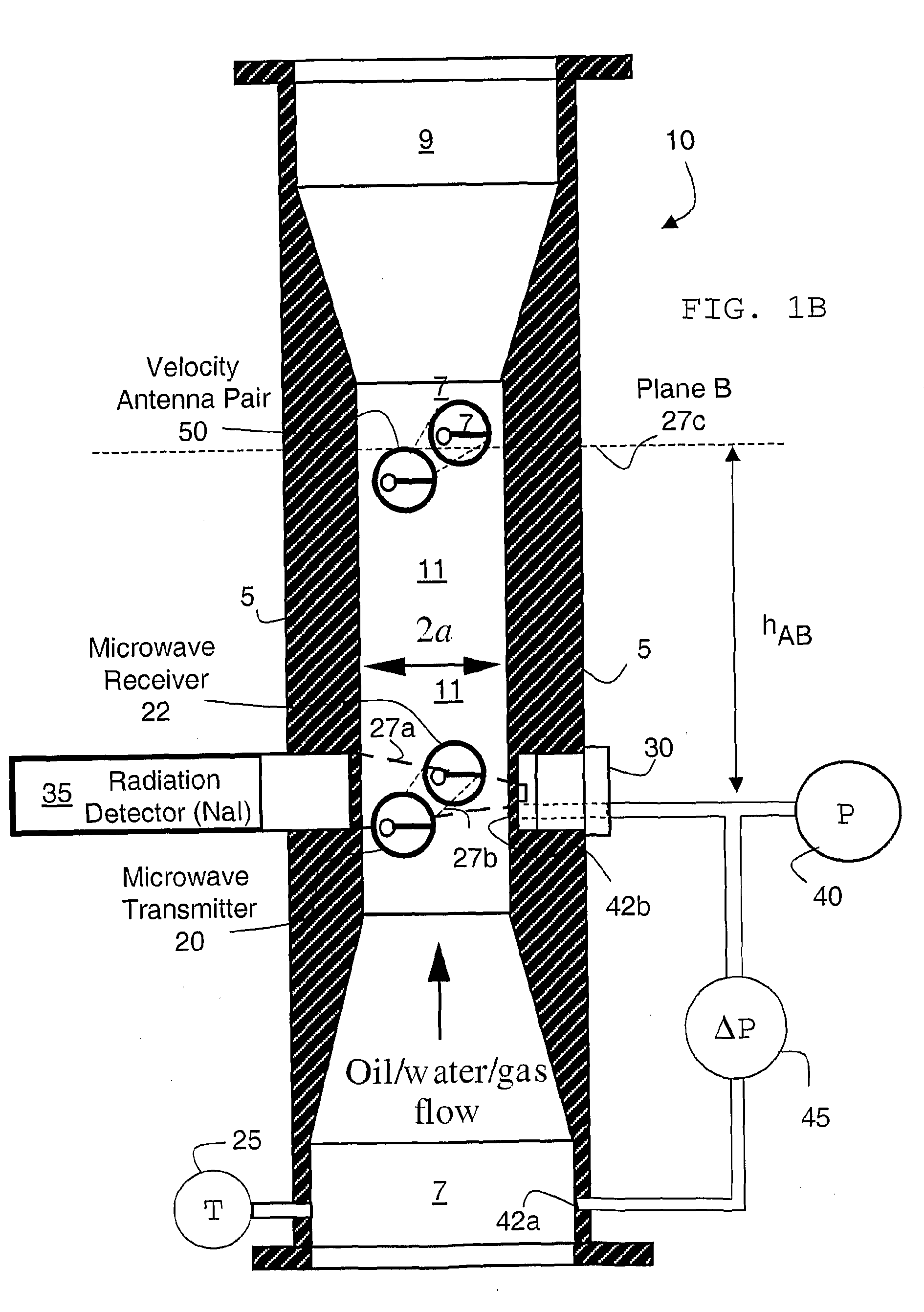
[0014]In a preferred embodiment of the present invention a low activity radiation source is used to determine an average density of the multiphase mixture passing through a perpendicular cross-section of the full-width pipeline or the throat section of the venturi, measuring a parameter that changes in relation to density changes in the multiphase mixture as it passes through the pipeline or the venturi, using measurements of the parameter to convert the average density to a “fast” density, measuring permittivity and / or conductivity of the multiphase mixture in the venturi and processing the multiphase flow of the multiphase mixture in the venturi from the fast density and one or a combination of the permittivity and conductivity. As the properties of the flow can vary rapidly in direction of the flow along the length of the pipe, the microwave measurement and the radiation density measurements in this preferred embodiment are taken over the same perpendicular cross-section of the pipe or throat. Microwave antennae and radiation source window and detector window to the flow are thus located at essentially at the same circumference of the pipe.

Problems solved by technology

It is, however, in general, very difficult to obtain measurements of the flow of the different phases when the different phases—oil, water and gas—flow simultaneously through the pipeline.
The problems associated with taking measurements arise, from among other things, the distribution of the three phases in the pipe—the phases may form different arrangements temporally and spatially—both axially and radially in the pipe.
However, in low flow velocity situations the oil and water may become partially or even completely separated.
For topside applications, however, it may be difficult to obtain high-accuracy flow rate measurements because of flow instabilities, including those discussed in more detail above, such as slug, chum, annular flow, etc.
Furthermore, due to these instabilities, it is often very difficult to measure water-cut using an in-line MPFM, especially for high gas-cuts.
While several different MPFMs have been designed to measure multiphase flow and / or phase content of the multiphase flow, as discussed below, these designs have many design drawbacks, such as requiring the use of high-activity / non-exempt radiation sources and the requirement of interpolation of measurements because of the configuration of the different measuring apparatus in the MPFM.
As such, the '020 patent does not disclose or teach measuring actual multiphase flow in a pipe and, consequently, it does not disclose how to address the issues associated with such measurements.
The method disclosed in the '020 patent has many limitations including but not limited to: the method is not robust—there is no solid physical basis for determining oil / water fraction purely from microwave attenuation; determining water cut based on amplitude attenuation may be inaccurate due to nonlinear attenuation effect; and the method does not provide for the use of low activity radiation sources.
Further, the '163 patent does not disclose using radiation density measurements in connection with the microwaves to make measurements that take account of multiphase fluid flow inconsistencies, including but not limited to flow inconsistencies caused by gas.

Method used


Image

  • Systems and Methods For Measuring Multiphase Flow in a Hydrocarbon Transporting Pipeline
  • Systems and Methods For Measuring Multiphase Flow in a Hydrocarbon Transporting Pipeline
  • Systems and Methods For Measuring Multiphase Flow in a Hydrocarbon Transporting Pipeline

Examples


Embodiment Construction

[0024]The ensuing description provides preferred exemplary embodiment(s) only, and is not intended to limit the scope, applicability or configuration of the invention. Rather, the ensuing description of the preferred exemplary embodiment(s) will provide those skilled in the alt with an enabling description for implementing a preferred exemplary embodiment of the invention. It being understood that various changes may be made in the function and arrangement of elements without departing from the spirit and scope of the invention as set forth in the appended claims.

[0025]Specific details are given in the following description to provide a thorough understanding of the embodiments. However, it will be understood by one of ordinary skill in the art that the embodiments maybe practiced without these specific details. For example, circuits may be shown in block diagrams in order not to obscure the embodiments in unnecessary detail. In other instances, well-known circuits, processes, algor...


PUM

PropertyMeasurementUnit
frequenciesaaaaaaaaaa

Abstract

This disclosure relates in general to methods and systems for measuring multiphase flows in a pipeline using a combination of venturi, microwave and radiation techniques, where the pipeline is configured to transport hydrocarbons. More specifically, but not by way of limitation, certain embodiments of the present invention provide methods and systems in which low activity radiation sources may be used in combination with one or more microwave transmitter-receiver pairs and pressure differential sensors to measure the flow rates and fractions of phases in multiphase flows in a pipeline, such as may be encountered in producing hydrocarbon wells. Additionally, other embodiments of the present invention provide for the arrangement of one or more microwave transmitter-receiver pairs, one or more radiation source-detector pairs and / or one or more pressure sensor ports in the same cross-section of the throat of a venturi to measure multiphase flow in a hydrocarbon transporting pipeline.

Description

BACKGROUND OF THE INVENTION[0001]This disclosure relates in general to methods and systems for measuring multiphase flows in a pipeline using a combination of venturi, microwave and radiation techniques, where the pipeline is configured to transport hydrocarbons. More specifically, but not by way of limitation, certain embodiments of the present invention provide methods and systems in which low activity radiation sources may be used in combination with one or more microwave transmitter-receiver pairs and a pressure differential sensor to measure the flow—fractions and rates of phases—in multiphase flows in a pipeline, such as may be encountered in producing hydrocarbon wells. Additionally, other embodiments of the present invention provide for the arrangement of one or more microwave transmitter-receiver pairs, one or more radiation source-detector pairs and / or one or more pressure sensor ports in the same cross-section of the throat of a venturi to measure multiphase flow in a hyd...

Claims


Application Information

Patent Timeline
Patent Type & Authority Applications(United States)
IPC IPC(8): G01F1/74G01N33/28G01N22/00G01N23/12
CPCG01N22/00G01N23/12G01N33/2823G01F1/44G01F1/74G01F1/663G01F1/708G01F1/712G01N9/24
Inventor XIE, CHENG-GANGKUHN DE CHIZELLE, YANJUNDT, JACQUES
Owner SCHLUMBERGER TECH CORP
Learn More