Firearm safety catch and trigger mechanism

Inactive Publication Date: 2009-01-01
QUIS TOMAS
View PDF17 Cites 2 Cited by
  • Summary
  • Abstract
  • Description
  • Claims
  • Application Information

AI Technical Summary

Benefits of technology

[0010]According to the invention, the modified parts include the bolt, the trigger mechanism feather, and the safety catch. The bolt is modified by narrowing its sides on its lower end by approximately 0.1 to 2 mm on each side so it would fit, when feeding the cartridges, in between the magazine feed lips of a new narrow single stack magazine. From the original trigger mechanism feather, its right hand arm, in the direction of the fire, is removed, which eliminates its co-operation with the right hand side striker catch and thus consequently with the trigger lever and the release lever. Because the right hand arm has been removed, any attempt to re-install the trigger lever and release lever, is prevented.
[0022]According to the invention, there is also provided, as a new part, a rivet in the receiver in a position to contact and prevent the turning of the safety catch rearwardly, thus establishing only a two position safety, making a stock with an integral grip and butt, and removing the assault rifle stock and replacing it with the integral grip and butt stock.

Problems solved by technology

But because most of these weapons have features typical of military weapons, ownership of these guns is strongly restricted and is reserved only to a small number of authorized enthusiasts.

Method used


Image

  • Firearm safety catch and trigger mechanism
  • Firearm safety catch and trigger mechanism
  • Firearm safety catch and trigger mechanism

Examples


Embodiment Construction

[0049]The particulars shown herein are by way of example and for purposes of illustrative discussion of the embodiments of the present invention only and are presented in the cause of providing what is believed to be the most useful and readily understood description of the principles and conceptual aspects of the present invention. In this regard, no attempt is made to show structural details of the present invention in more detail than is necessary for the fundamental understanding of the present invention, the description taken with the drawings making apparent to those skilled in the art how the several forms of the present invention may be embodied in practice.

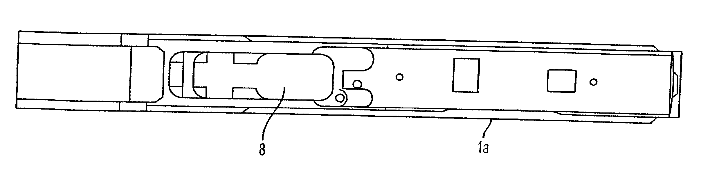
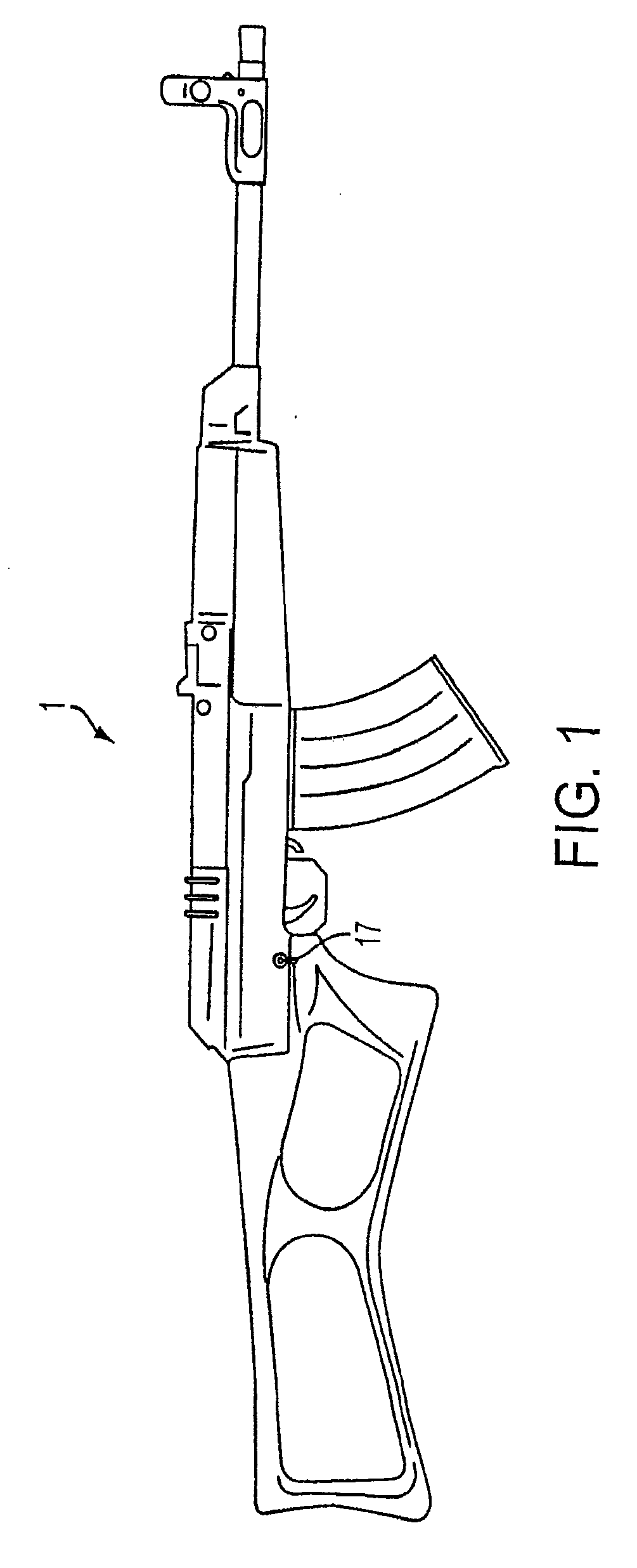
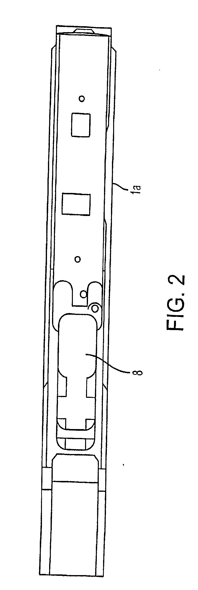
[0050]As can be seen in FIG. 1, the converted semi-automatic sporter rifle 1 retains the original appearance of an Sa vz. 58 model military automatic rifle, but has been created partly from original parts of an Sa vz. 58 assault rifle, partly from modified parts, and partly from newly manufactured parts.

[0051]Some parts o...


PUM


Abstract

A trigger mechanism of a firearm is modified by having its right hand side (in the direction of fire) arm, removed, while leaving the left hand side arm intact, which eliminates its co-operation with a right hand side striker catch, consequently preventing an attempt to reinstall the removed parts. In a second version, the trigger mechanism is manufactured without its right arm. The safety catch is modified by inserting a groove near a far end such that it is configured to receive a firearm interrupter, enabling its manning and firing of a single shot when the firearm is in the horizontal position, while preventing the firearm from shooting when in a vertical position.

Description

RELATED APPLICATIONS[0001]This application is a CIP Application of application Ser. No. 11 / 969,014, filed Jan. 3, 2008, entitled “Semi-Automatic Sporting Rifle,” which is a Divisional Application of U.S. application Ser. No. 11 / 245,118, filed Oct. 7, 2005, entitled “Semi-Automatic Rifle SA VZ. 58” and issued on May 20, 2008 as U.S. Pat. No. 7,373,868. The subject matter of both patent applications is hereby incorporated by reference herein in their entirety. Additionally, reference is made herein to another concurrently filed CIP application related to the above-mentioned applications, and bearing docket number P17230 CIPI.BACKGROUND OF THE INVENTION[0002]1. Field of the Invention[0003]The invention relates to firearms, and specifically to rifles similar to military weapons, but modified to be appropriate for civilian, sporting use.[0004]This particular invention converts the Czech model Sa vz. 58 to a semi automatic sporting rifle.[0005]2. Discussion of Background Information[0006]...

Claims


Application Information

Patent Timeline
IPC IPC(8): F41A19/00F41A17/00
CPCF41A11/00F41A17/08F41A17/10F41A35/00F41A19/02F41A19/33F41A17/56
Inventor QUIS, TOMAS
Owner QUIS TOMAS
Why Eureka
Try Eureka