High speed cotton picker drum

a cotton picker and high-speed technology, applied in the field of cotton pickers, can solve the problems of limiting the rotational speed, affecting the synchronization of the spindle/plant zone, and dictating the maximum harvest speed, so as to improve the angular positioning of the spindle, reduce the destructive effect of the high-speed cotton picker and reduce the destructive effect of the drum speed

Active Publication Date: 2009-01-01
DEERE & CO
View PDF9 Cites 1 Cited by
  • Summary
  • Abstract
  • Description
  • Claims
  • Application Information

AI Technical Summary

Benefits of technology

[0005]The present invention reduces destructive effects of cotton picker high rotational drum speed by more closely synchronizing the rearward spindle tip motion with the forward speed of the cotton picker, in part by use of improved angular positioning the spindles in the picking zone. An improved cam track arrangement of the present invention angularly positions the spindles so that spindle tip spacing in a substantial portion of the picking zone is equal to spindle base spacing in the extremities to thereby maintain closer plant / spindle synchronization over a substantial portion of the zone. Only in one portion of the picking zone are the spindle tips closer together than the spindle bases. Over the remainder of the picking zone, the spindle speed is more closely synchronized to the harvester speed. Rearward spindle tip motion is adjusted by the angular positioning of the spindle bars by the cam arrangement. The cam rotates the picker bar about the upright axis of the bar to vary the speed of the spindle tip in the picking zone and allow a higher drum speed. As a result, a higher cotton picker vehicle ground speed can be achieved without loss of picking efficiency and without any additional damage to the cotton plants that are being picked. In one embodiment, for example, the drum with the improved cam configuration facilitates increases in the maximum harvester speed from about 14% to 25% compared to a conventional cam configuration without loss of picking efficiency or additional damage to the cotton plants being picked. The improved cam configuration also provides smoother picker bar pivoting action to avoid excessive bearing forces and reduce slinging of cotton from the spindles.

Problems solved by technology

The picker drums present a large mass in motion with numerous rotating parts and therefore have a limited rotational speed.
The drum speed limitation dictates the maximum harvest speed of the picker.
This angular positioning of the spindles increased the spindle density in the picking zone but actually compromised spindle / plant synchronization in the zone since the effect of decreasing spacing was to slow the rearward speed of spindles in the zone.
Therefore, forward harvester speed was limited by the slowing of the spindles in the picking zone.

Method used


Image

  • High speed cotton picker drum
  • High speed cotton picker drum
  • High speed cotton picker drum

Examples


Embodiment Construction

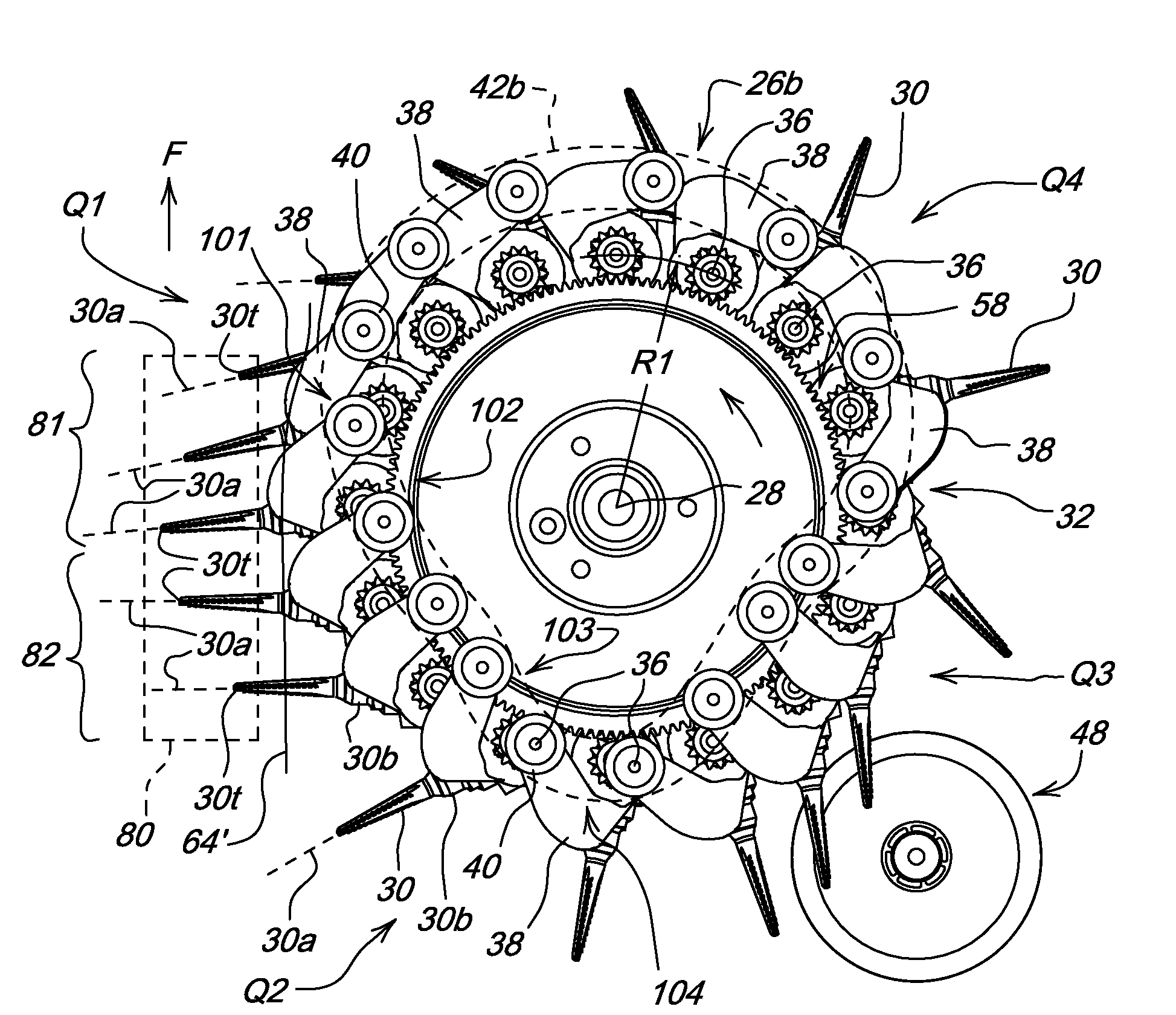
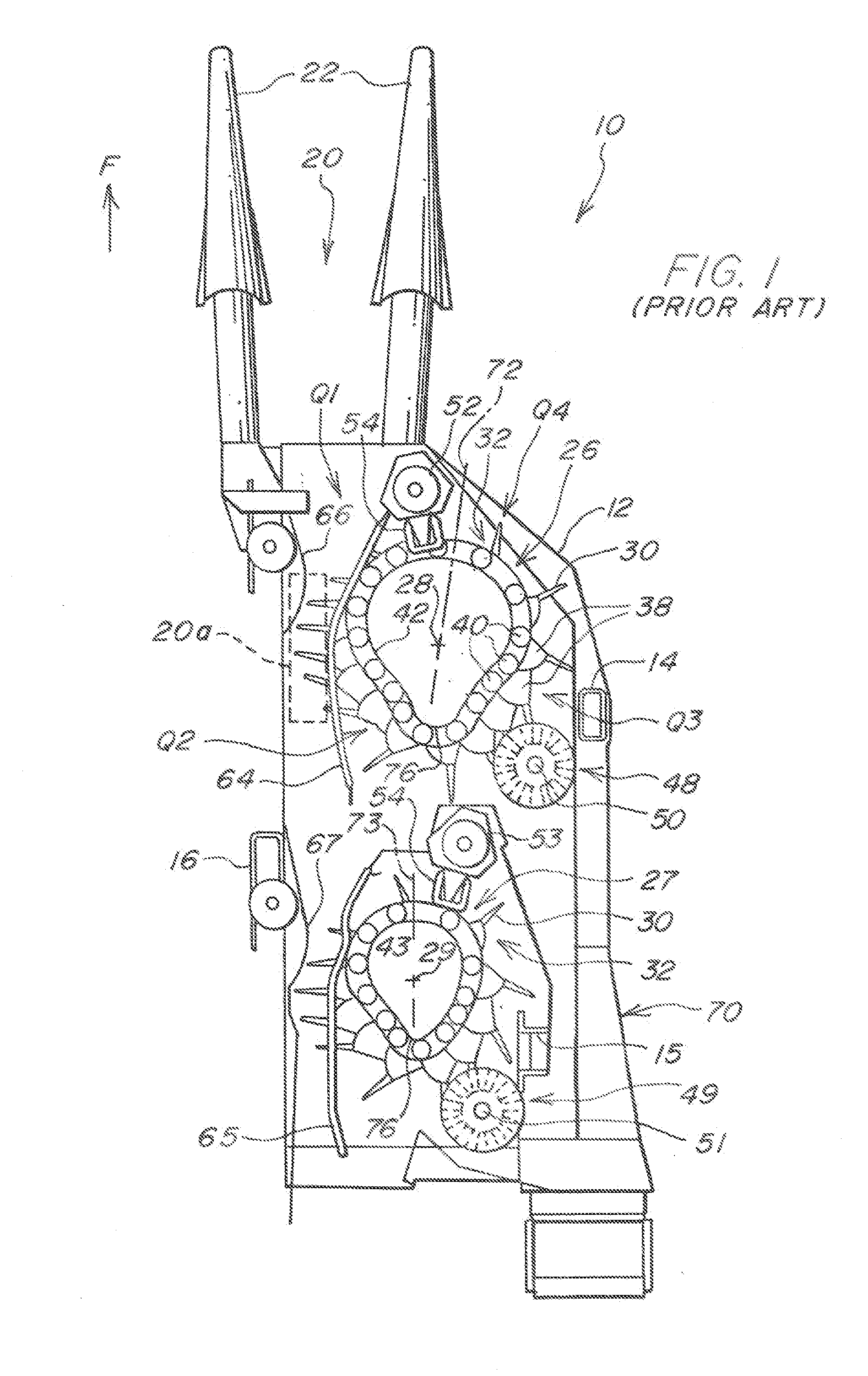
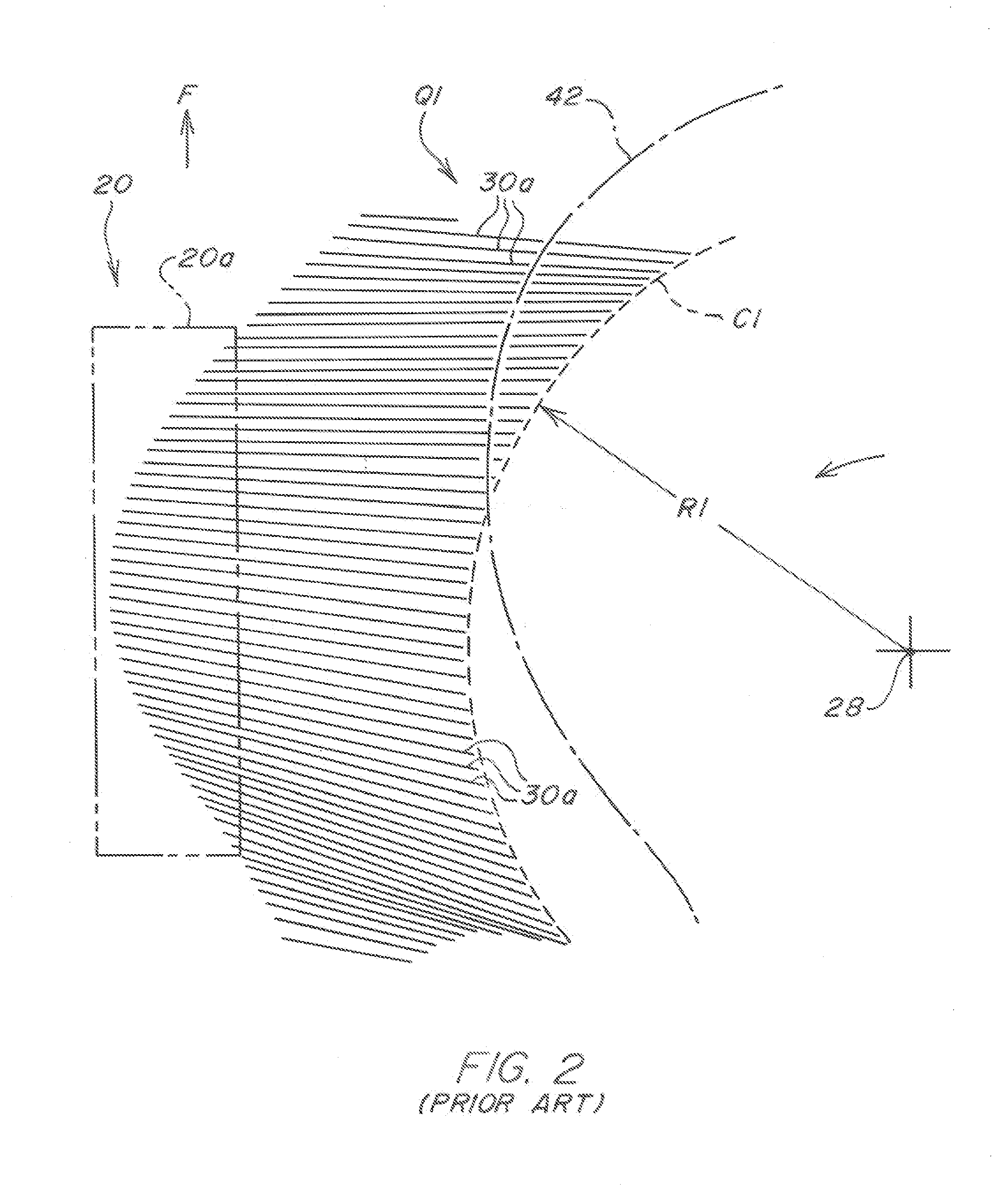
[0010]Referring now to FIG. 1 therein is shown a conventional row unit 10 for a cotton picker. The row unit 10 includes a housing 12 with upright structural members such as shown at locations 14, 15 and 16. A fore-and-aft extending row-receiving area 20 is defined which extends rearwardly from between a pair of stalk lifters 22 through to the rear of the housing 12. Front and rear upright picker drums 26 and 27 with upright rotational axes 28 and 29 are supported within the housing 12 and include spindles 30 supported in rows by a plurality of upright spindle or picker bars 32. The spindles 30 include rows of barbs (not shown) extending generally in the direction of rotation of the spindles. The picker bars 32 are supported for rotation about upright axes such as shown at 36 in FIG. 3 uniformly spaced about a circle C1 of radius R1 which centers on the rotational axis 28 of the drum. Each picket bar 32 includes a cam arm 38 with an upper cam roller 40 supported within the track of a...


PUM


Abstract

To reduce destructive effects of cotton picker high speed drum rotation, rearward spindle tip motion is adjusted in part by angularly positioning the spindles in the picking zone with an improved cam track arrangement. The cam rotates the picker bar about the upright axis of the bar to vary the speed of the spindle tip in the picking zone and allow a higher drum speed. In a first portion of the picking zone the spindle tips are closer together than the spindle bases at the picker bar. The spindle tip spacing in a second portion of the picking zone is approximately equal to spindle base spacing in the extremities. The resulting spindle tip movement facilitates higher cotton picker vehicle ground speed without picking efficiency loss or additional damage to the cotton plants.

Description

FIELD OF THE INVENTION[0001]The present invention relates generally to cotton pickers and, more specifically, to the harvesting drum on a cotton picker row unit.BACKGROUND OF THE INVENTION[0002]A typical spindle-type cotton picker includes upright cotton picker drums with bars or columns of rotating spindles that engage the cotton plants. The drums are rotated so the rearward motion of the spindles in the picking zone is synchronized to the forward speed of the picker to generally obtain zero relative velocity between the cotton plant and the spindles engaging that cotton plant.[0003]The picker drums present a large mass in motion with numerous rotating parts and therefore have a limited rotational speed. The drum speed limitation dictates the maximum harvest speed of the picker. Attempts to increase picker speed have concentrated on reduction of drum mass, better lubrication of the rotating elements that experience increased friction with increased speed, and minimization of accele...

Claims


Application Information

Patent Timeline
Patent Type & Authority Applications(United States)
IPC IPC(8): A01D46/18
CPCA01D46/18
Inventor JOHANNSEN, DANIEL JOHNFOX, JEFFREY ROBERTPHILIPS, MARK SAMUEL
Owner DEERE & CO
Why Eureka
Try Eureka