Bearing Assembly with a Strain Sensor

Inactive Publication Date: 2009-01-01
SKF GROUP HEADQUARTERS +1
View PDF8 Cites 0 Cited by
  • Summary
  • Abstract
  • Description
  • Claims
  • Application Information

AI Technical Summary

Benefits of technology

[0004]It is an aim of the invention to provide a bearing and shaft assembly with at least one strain sensor for a bearing and shaft arrangement that has an impro

Problems solved by technology

Such an arrangement has the disadvantage that the bearing ring needs to be a stiff element to properly support the rolling elements, with as little misal

Method used


Image

  • Bearing Assembly with a Strain Sensor
  • Bearing Assembly with a Strain Sensor

Examples


Example

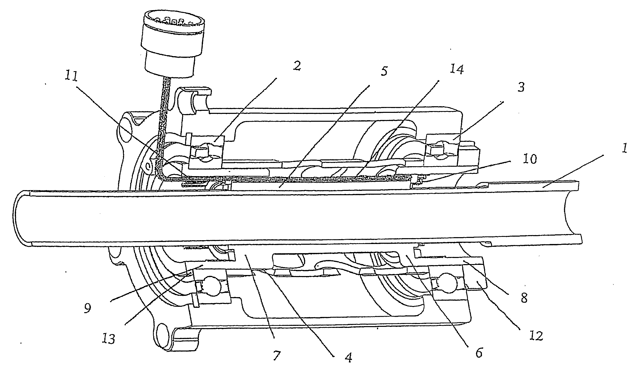
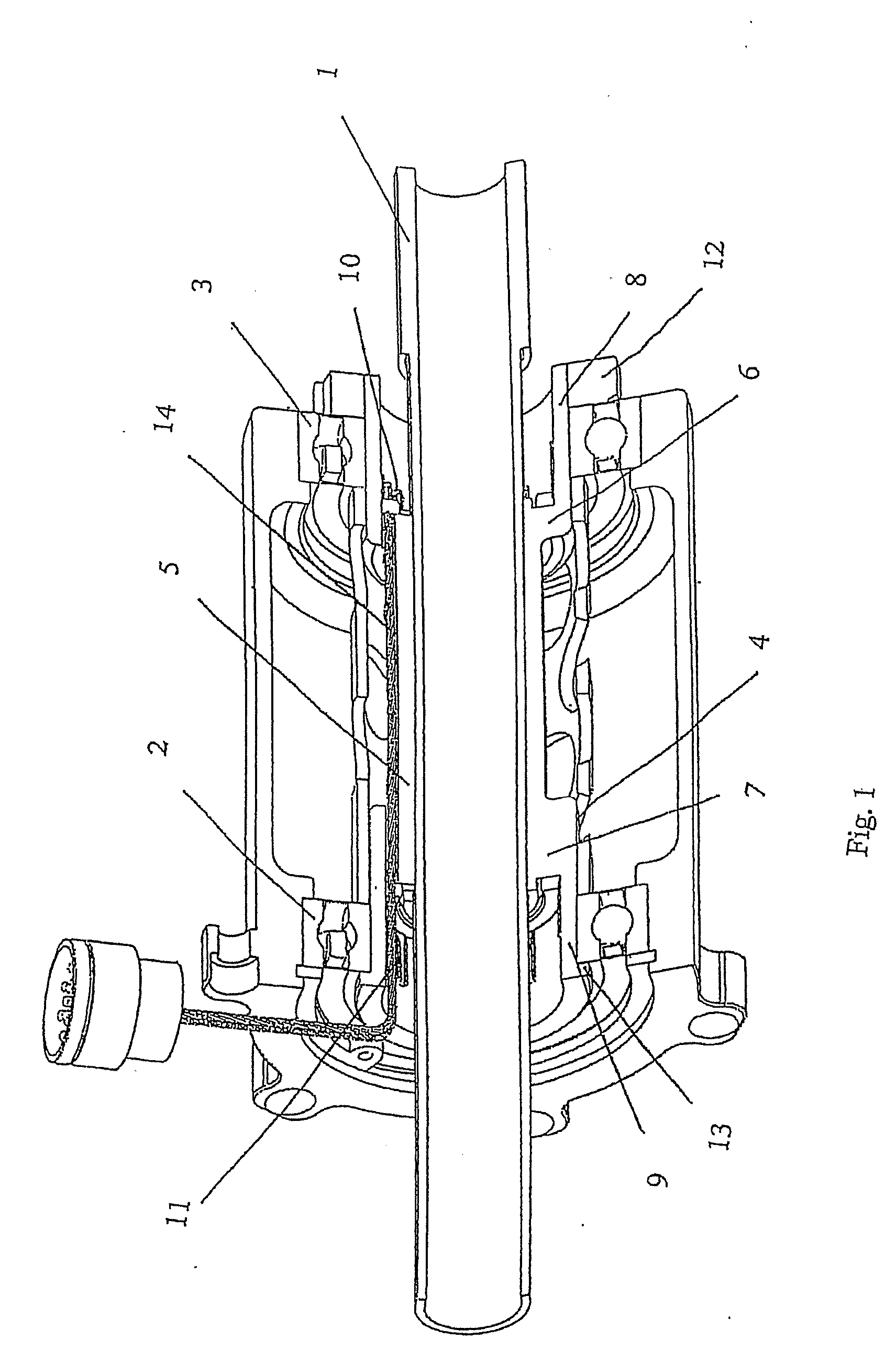
[0015]In FIG. 1 a shaft 1 is shown, and two bearings 2, 3 are mounted on a elastic component 4, which in turn is mounted on shaft 1. The bearing and shaft assembly forms part of a wheel of a motor cycle.

[0016]Elastic component 4 comprises a middle section 5 that is in direct contact with shaft 1. At each of the opposing ends of middle section 5, elastic component 4 is formed with steps 6, 7, and further extending outward in axial direction respectively overhung parts 8, 9. Bearings 2, 3 are mounted on respectively overhung parts 9, 8 of elastic component 4.

[0017]Elastic component 4 comprises at the overhung parts 8, 9, at the inside in radial direction, strain sensor assemblies 10, 11 respectively. Strain sensor assemblies 10, 11 each comprise three separate strain sensors, suitably positioned on the inner circumference of respectively overhung parts 8, 9 of elastic component 4. This arrangement enables measurements, not only of vertical load on the motor cycle wheel, but at the sam...


PUM


Abstract

A bearing and shaft assembly comprises a shaft and at least one bearing, and is provided with at least one strain sensor. An elastic component is provided between the shaft and the at least one bearing, and the elastic component comprises the at least one strain sensor. In one disclosed embodiment, the elastic component forms an integral part with one of the bearing and the shaft.

Description

TECHNICAL FIELD[0001]The invention relates to a bearing and shaft assembly, comprising a shaft and at least one bearing, and provided with at least one strain sensor.BACKGROUND[0002]Strain sensors are used to measure load. The signal from the strain sensor is then processed to represent a load value. Load measuring in a bearing is known e.g. from DE 102 50 340, where a load measuring bearing comprises strain gauges that are mounted as a thick film on one of the bearing rings. The bearing ring is formed with a slot in which during heat treatment of the ring the thick film with the strain gauge is burned.[0003]Such an arrangement has the disadvantage that the bearing ring needs to be a stiff element to properly support the rolling elements, with as little misalignment of the rolling elements under load as possible. Because of this stiffness of the bearing rings the resolution of the strain-gauges is very limited. As a result only forces that act in the weakest direction of the bearing...

Claims


Application Information

Patent Timeline
IPC IPC(8): G01L1/22F16C19/52F16C27/00
CPCF16C19/54F16C27/04F16C2326/20F16C19/522G01L5/0009
Inventor MOL, HENKZAAIJER, ERIKFALSETTI, FABIOVISSERS, CARL
Owner SKF GROUP HEADQUARTERS
Why Eureka
Try Eureka