Control Device

a technology of control device and control element, which is applied in the direction of mechanical control device, gearing, instruments, etc., can solve the problems of not being able to be assigned unambiguously, erroneous or non-functioning recognition or detection of the position of the control element, and the operating state of the windshield wiper cannot be changed. the effect of the switching state of the control elemen

Active Publication Date: 2009-01-01
ZF FRIEDRICHSHAFEN AG
View PDF9 Cites 56 Cited by
  • Summary
  • Abstract
  • Description
  • Claims
  • Application Information

AI Technical Summary

Benefits of technology

[0012]Against this background, the object of the present invention is to provide a means for the electronic or generally by-wire actuation of a technical system, with which the drawbacks of the state of the art can be overcome. In particular, the control device shall make possible just as intuitive and easy-to-understand an actuation of the technical system as this has always been the case with mechanical or electromechanical actuating elements, for example, toggle switches. An immediate, intuitive and unambiguous feedback of the state of the system during the control of the corresponding actuating system shall also be an essential aspect.

Problems solved by technology

However, the electrical or electronic actuation of such systems, which makes do without mechanical connection, entails that there may sometimes not be an unambiguous assignment between the position of an actuating element and the state of the system that can be controlled by means of the actuating element, for example, a vehicle transmission.
For example, erroneous or non-functioning recognition or detection of the position of the control element may occur, with the consequence that the gear, preselected, for example, by the driver with the control element, was not recognized by the system and the corresponding control command was not therefore sent to the transmission.
However, the situation that technical systems, for example, vehicle transmissions, automatically adapt their operating or switching state to changed general conditions and change them without direct action on the part of the driver also occurs increasingly frequently in modern motor vehicles with the increasingly interconnected, complex technical systems used there.
However, this means that the operating state of the windshield wiper will no longer possibly agree with the switching state of the control element for the windshield wiper.
Even if the actual operating position may be easily recognizable in case of the windshield wiper, at least the problem still remains that the actuating element is already in the off position when manual intervention with the automatic system of the windshield wiper is possibly desirable, i.e., to turn off the windshield wiper.
Aside from the lack of control comfort of a man-machine interaction of such a design, such complicated control concepts can obviously also lead to undesired consequences in terms of the concentration of the driver on the actual driving action, and thus to problems with driving safety.

Method used


Image

  • Control Device
  • Control Device
  • Control Device

Examples


Embodiment Construction

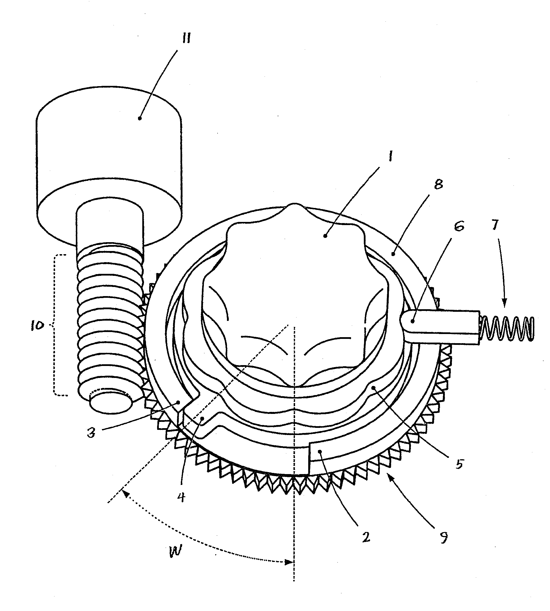
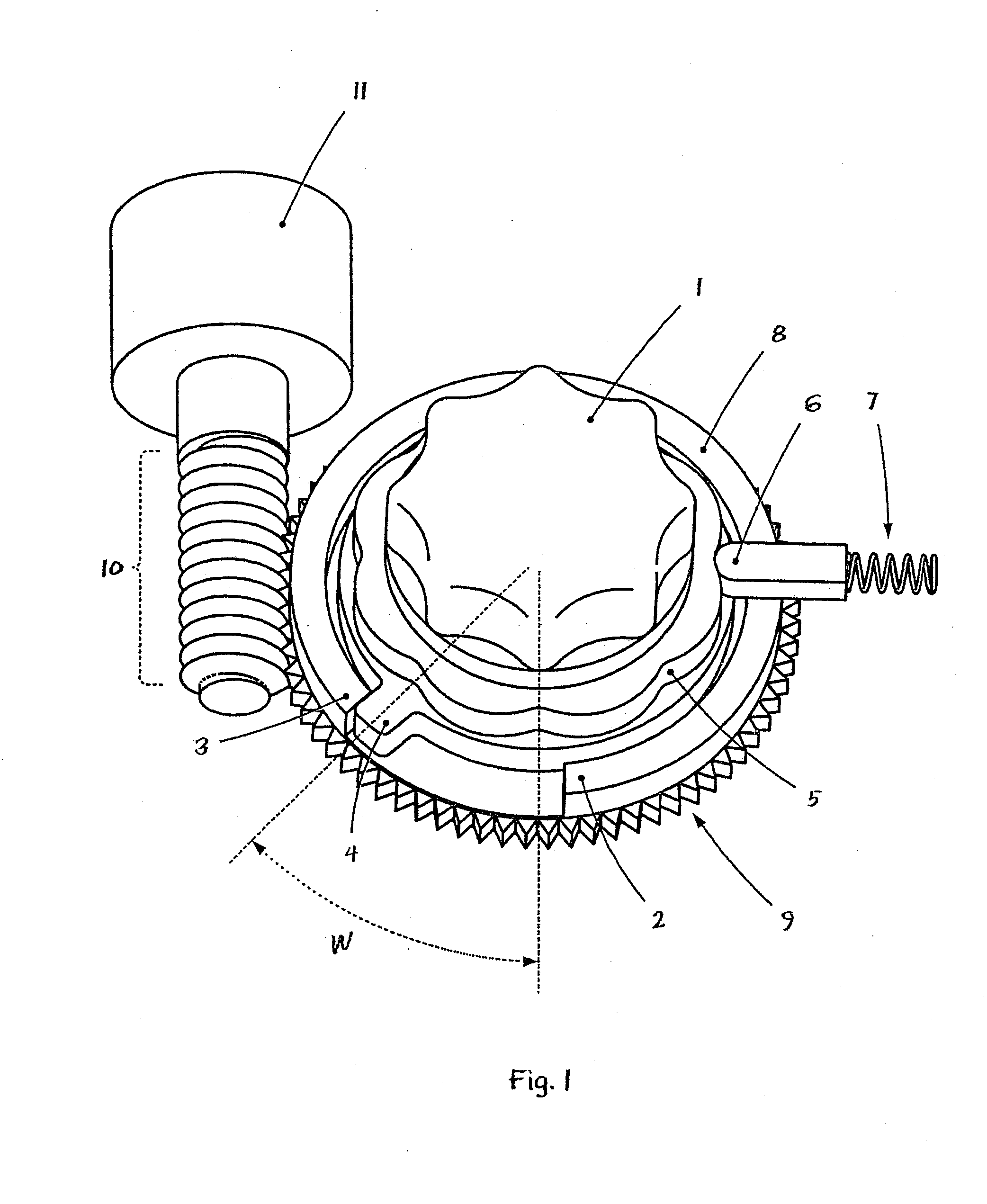
[0048]Referring to the drawings in particular, FIG. 1 shows a schematic isometric view of the actuating element 1 and the stop means 2, 3 of a control device according to the present invention.

[0049]The actuating element, which is designed as a rotationally symmetrical turning knob 1 with recessed grip for the fingers and is used to control a technical system, not shown, is recognized at first. It shall be assumed for the sake of simple illustration only that the turning knob 1 being shown shall be used to switch a windshield wiper on and off.

[0050]The turning knob 1 is connected in one piece to a locking contour 5 extending circumferentially in an annular pattern, on which a spring-loaded locking piece 6 slides. The locking piece 6 and the compression spring 7 are arranged in a corresponding recess in the housing of the control device, which said housing is not being shown here. The locking contour 5 ensures a perceptible snapping in of the turning knob 1, in the sense of the ergon...


PUM


Abstract

A control device is provided for a technical system (17), e.g. for a shift-by-wire vehicle transmission. The control device includes a control (actuating) element, e.g. a rotary knob (1), with at least two shifting positions. The control element (1), itself, can rotate without limitation, whereas the control device has at least one stop device (2, 3), which can be adjusted in a controlled manner and which limits the angle of rotation (W) of the control element (1).

Description

CROSS REFERENCE TO RELATED APPLICATIONS[0001]This application is a United States National Phase application of International Application PCT / DE2005 / 001485 and claims the benefit of priority under 35 U.S.C. § 119 of German Patent Application DE 10 2004 041 087.9 filed Aug. 24, 2004, the entire contents of which are incorporated herein by reference.FIELD OF THE INVENTION[0002]The present invention pertains to a device for actuating or controlling a technical system, for example, for actuating the gears of a vehicle transmission and more particularly for a shift-by-wire vehicle transmission, the control device having an actuating element with at least two shift positions.BACKGROUND OF THE INVENTION[0003]Control device of the type mentioned in the introduction are used, for example, but by no means exclusively, in motor vehicles for actuating many different systems and functions of the motor vehicle. Numerous systems and functions are operated electrically and controlled electronically ...

Claims


Application Information

Patent Timeline
Patent Type & Authority Applications(United States)
IPC IPC(8): F16H35/18
CPCB60K37/06B60K2350/102F16H59/08F16H61/24G05G1/10Y10T74/2003G05G5/04G05G5/06F16H2059/081Y10T74/2014G05G5/03B60K2370/126B60K2370/158
Inventor MEYER, JOERGGIEFER, ANDREAS
Owner ZF FRIEDRICHSHAFEN AG
Why Eureka
Try Eureka