Compressed hub damper

a hub damper and compression technology, applied in the direction of spring/damper, rotating vibration suppression, vibration suppression adjustment, etc., can solve the problems of rotatable shaft fatigue failure, relatively laborious, and considerable amplitude of torsional vibrations

Active Publication Date: 2009-01-01
DAYCO IP HLDG
View PDF19 Cites 26 Cited by
  • Summary
  • Abstract
  • Description
  • Claims
  • Application Information

AI Technical Summary

Benefits of technology

[0005]The present invention is premised on the realization that a torsional vibration damper with a large inertia in a minimal space can be formed by having an inertia member that extends approximately from the central opening of hub of the damper to the perimeter of the damping / absorption. Separate front and rear hub members are fastened together with the inertia mass held between the hub members. Annular elastomeric rings are located between the hub members and the inertia mass to provide the vibration damping. Fasteners extend through the hub members and the inertia member with a clearance provided between the inertia mass and the fasteners. This allows movement of the inertia mass relative to the hub members.

Problems solved by technology

The torsional vibrations may have a considerable amplitude and, if not abated, can potentially damage gears or similar structures attached to the rotatable shaft and cause fatigue failure of the rotatable shaft.
This is relatively labor intensive.
Further, with this design, assembly is problematic.
This requires special equipment which, in turn, increases the cost of the damper.

Method used


Image

  • Compressed hub damper
  • Compressed hub damper
  • Compressed hub damper

Examples


Embodiment Construction

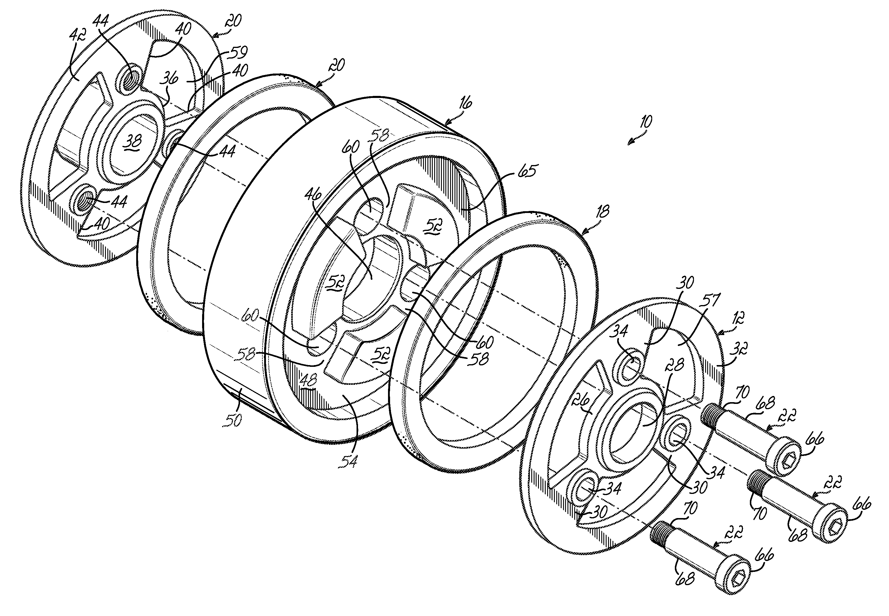
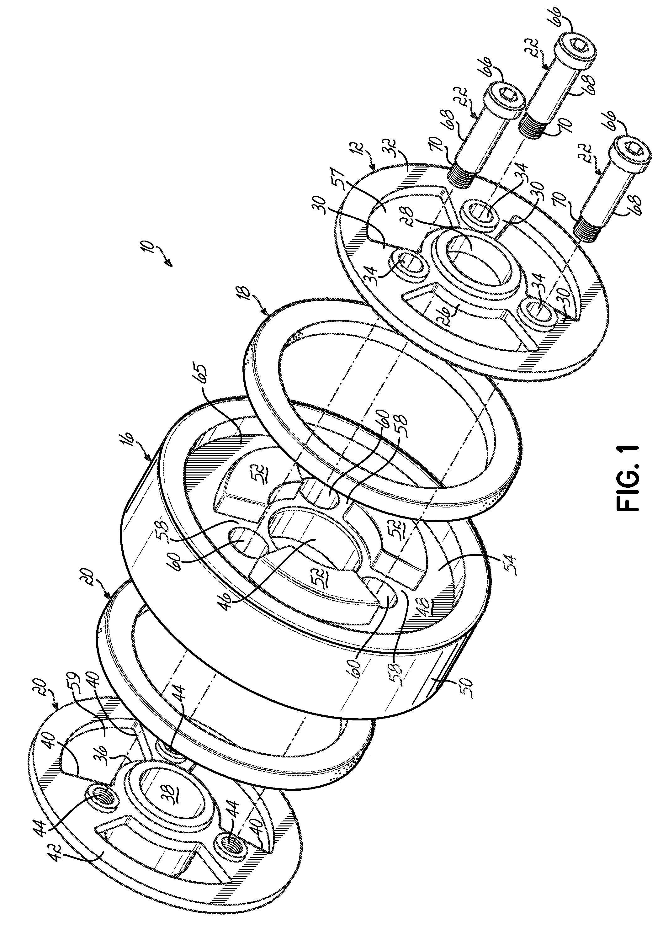
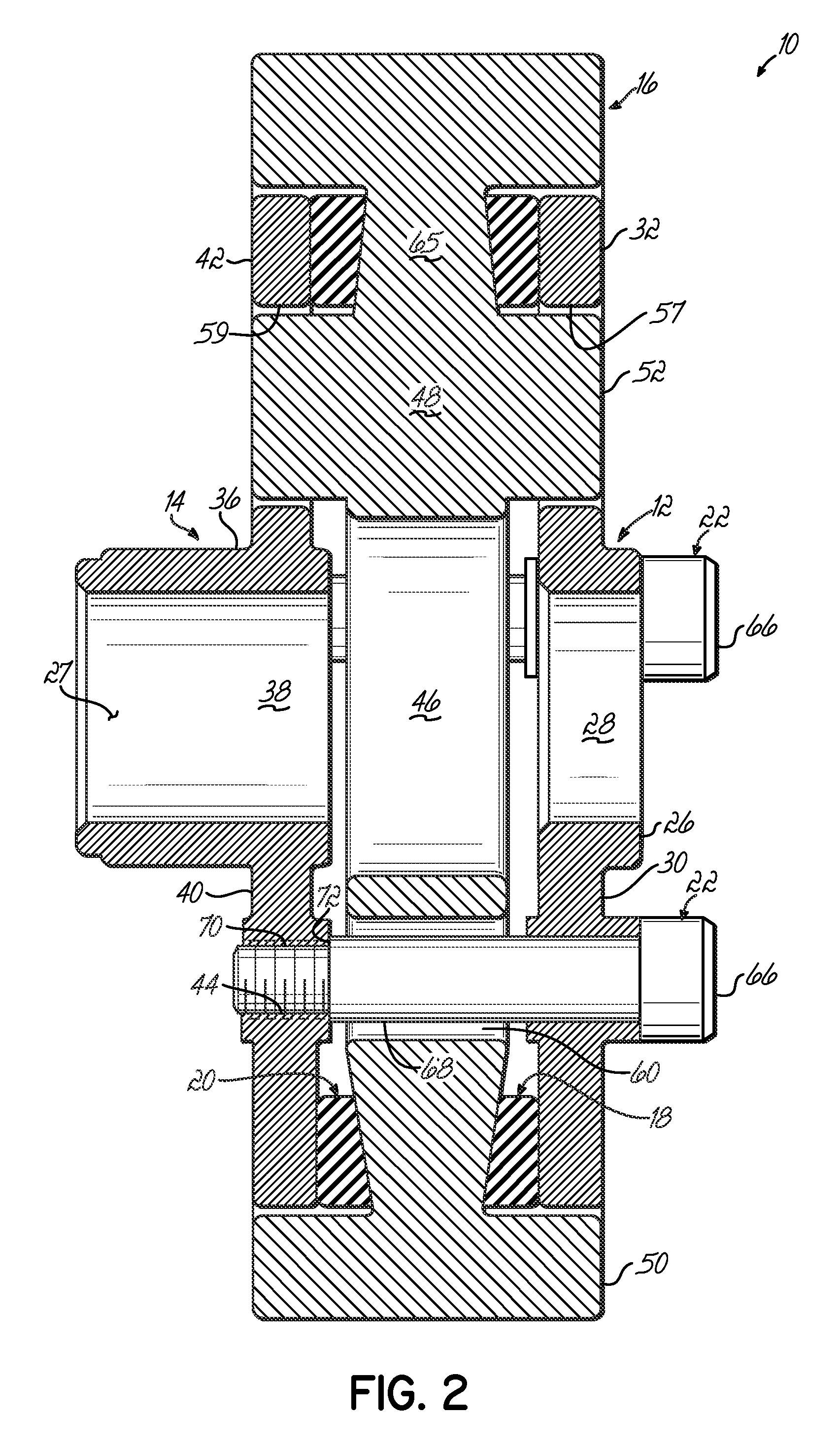
[0012]As shown in FIGS. 1 and 2, damper 10 includes a first hub member 12, a second hub member 14, an inertia mass 16, and first and second compressible or elastomeric rings 18 and 20. This damper 10 is held together with shoulder bolts 22 and attaches to crankshaft 24.

[0013]The first hub member 12 includes a first central hub 26 having a first central opening 28 with spokes 30 extending radially outwardly from hub 26 to an annular ring 32. There are a series of holes or openings 34 between spokes 30.

[0014]Likewise, second hub member 14 includes a second hub 36 with a second central opening 38. The hub member 14 further includes spokes 40 that extend radially outward from the second hub 36 and extend to an outer annular ring 42. Internally threaded holes 44 extend through the spokes 40. As shown, the second hub 36 of second hub member 14 is axially elongated to provide an engaging surface 27 with a shaft (not shown).

[0015]In turn, the inertia mass 16 includes a central opening 46 th...


PUM


Abstract

A torsional vibration damper includes front and rear hub members with an inertia mass between the two hub members. Annular elastomeric rings are positioned between the front and rear hub members and the inertia mass holding the inertia mass. Fasteners extend through the front hub member, the inertia mass, and fixed to the rear hub member. A clearance between the fastener and the inertia mass allows relative motion to absorb torsional vibration.

Description

FIELD OF THE INVENTION[0001]The invention relates to torsional vibration dampers and, in particular, to vibration dampers adapted to be mounted on rotatable shafts such as the crankshaft of an internal combustion engine.BACKGROUND OF THE INVENTION[0002]Torsional vibration dampers are employed extensively in internal combustion engines to reduce torsional vibrations delivered to rotatable shafts. The torsional vibrations may have a considerable amplitude and, if not abated, can potentially damage gears or similar structures attached to the rotatable shaft and cause fatigue failure of the rotatable shaft. Torsional vibration dampers absorb vibration and, to a certain extent, reduce the amplitude of the vibrations by converting the vibrational energy to thermal energy as a result of the damping action. The absorption of the vibrational energy lowers the strength requirements of the rotatable shaft and, therefore, lowers the required weight of the shaft. The torsional vibration damper a...

Claims


Application Information

Patent Timeline
Patent Type & Authority Applications(United States)
IPC IPC(8): F16F15/12
CPCY10T74/2131F16F15/126
Inventor CHRISTENSON, BRUCE G.MANZOOR, SUHALE
Owner DAYCO IP HLDG
Why Eureka
Try Eureka