System and process for gas sweetening

a gas sweetening and system technology, applied in the field of desulfurization of gas streams, can solve the problems of corroding sulfuric acid to the metals of process apparatuses, acid rain production and potential environmental destruction, and the production of sulfuric acid, etc., to increase the rate of multiphase process, reduce overall cost, and increase the product per unit of catalyst consumed

Inactive Publication Date: 2009-01-01
HRD CORP
View PDF10 Cites 6 Cited by
  • Summary
  • Abstract
  • Description
  • Claims
  • Application Information

AI Technical Summary

Benefits of technology

[0016]Some embodiments of the system potentially make possible the sweetening of gas streams without the need for large volume reactors, via use of an external pressurized high shear reactor.
[0017]Certain embodiments of an above-described method or system potentially provide for more optimal time, temperature and pressure conditions than are otherwise possible, and which potentially increase the rate of the multiphase process. Certain embodiments of the above-described methods or systems potentially provide overall cost reduction by operating at lower temperature and / or pressure, providing increased product per unit of catalyst consumed, decreased reaction time, and / or reduced capital and / or operating costs. These and other embodiments and potential advantages will be apparent in the following detailed description and drawings.

Problems solved by technology

Combustion of hydrogen sulfide produces sulfur dioxide, which is believed to lead to the production of acid rain and potential destruction of the environment.
Furthermore, when contacted with water, hydrogen sulfide forms sulfuric acid which is corrosive to the metals of process apparatus.
Such low head oxidizers are relatively poor mass transfer devices.
Low head oxidizers do, however, provide much needed solution inventory for proper operation of the system.
These oxidizers provide mass transfer coefficients which are approximately 4 times better than those of low head oxidizers; however, this is at the expense of higher discharge heads on the air blowers.

Method used


Image

  • System and process for gas sweetening
  • System and process for gas sweetening
  • System and process for gas sweetening

Examples


Embodiment Construction

Overview

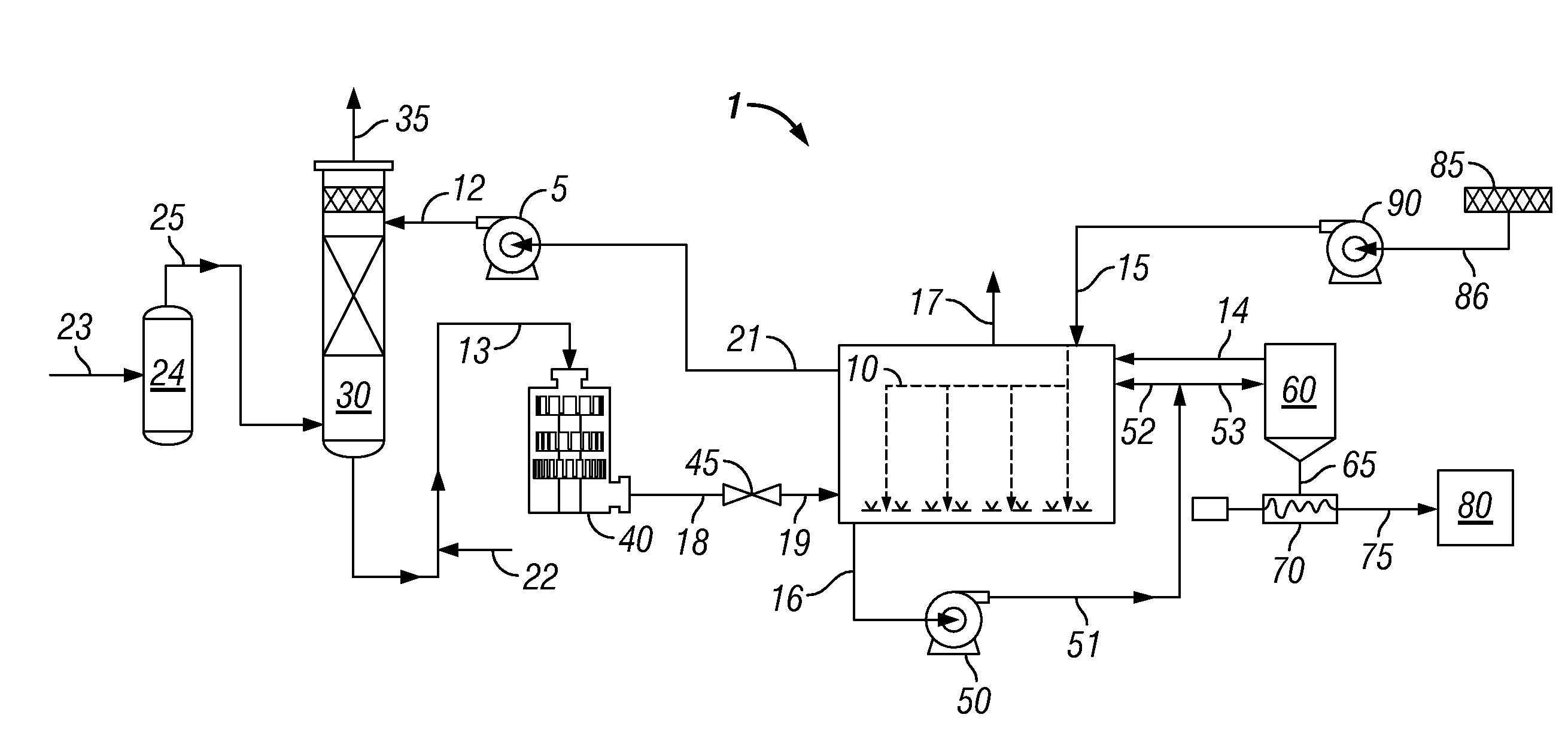
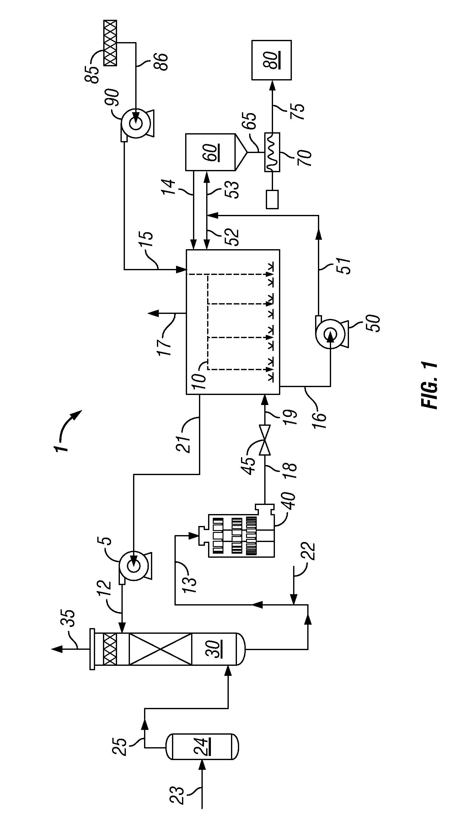
[0023]The rate of chemical reactions involving liquids, gases and solids depend on time of contact, temperature, and pressure. In cases where it is desirable to react two or more raw materials of different phases (e.g. solid and liquid; liquid and gas; solid, liquid and gas), one of the limiting factors controlling the rate of reaction involves the contact time of the reactants. In the case of heterogeneously catalyzed reactions there is the additional rate limiting factor of having the reacted products removed from the surface of the catalyst to permit the catalyst to catalyze further reactants. Contact time for the reactants and / or catalyst is often controlled by mixing which provides contact with two or more reactants involved in a chemical reaction.

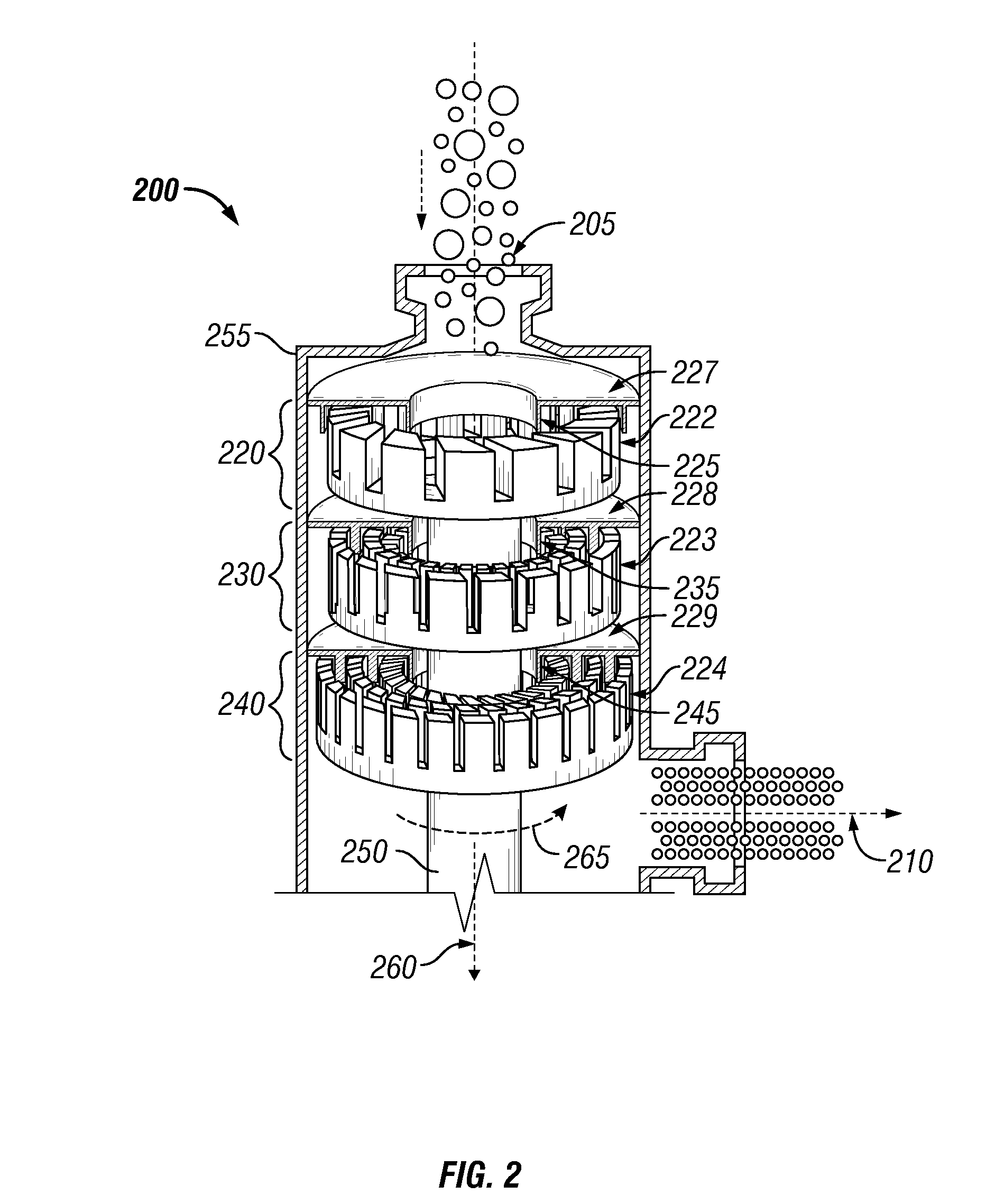
[0024]A reactor assembly that comprises an external high shear device or mixer as described herein makes possible decreased mass transfer limitations and thereby allows the reaction to more closely approach kinetic limitations...


PUM

PropertyMeasurementUnit
diameteraaaaaaaaaa
mean diameteraaaaaaaaaa

Abstract

A method for removing hydrogen sulfide from a sour gas stream comprising hydrogen sulfide by oxidizing hydrogen sulfide in a converter by contacting the sour gas stream with an aqueous catalytic solution, thereby producing a desulfurized gas stream and a liquid stream comprising reduced catalyst and elemental sulfur, introducing an oxidant and the liquid stream comprising reduced catalyst and elemental sulfur into a high shear device and producing a dispersion wherein the mean bubble diameter of the oxidant gas in the dispersion is less than about 5 μm, introducing the dispersion into a vessel from which a sulfur-containing slurry is removed and a regenerated catalyst stream is removed, wherein the sulfur slurry comprises elemental sulfur and aqueous liquid, and recycling at least a portion of the regenerated catalyst stream to the converter. A system of apparatus for carrying out the method is also provided.

Description

CROSS-REFERENCE TO RELATED APPLICATIONS[0001]This application claims the benefit under 35 U.S.C. §119(e) of U.S. Provisional Patent Application No. 60 / 946,459 entitled “High Shear Gas Sweetening Process,” filed Jun. 27, 2007 the disclosure of which is hereby incorporated herein by reference.STATEMENT REGARDING FEDERALLY SPONSORED RESEARCH OR DEVELOPMENT[0002]Not Applicable.BACKGROUND OF THE INVENTION[0003]1. Technical Field[0004]The present invention generally relates to the desulfurization of gas streams containing hydrogen sulfide. More particularly, the present invention relates to a high shear system and method for catalytically oxidizing hydrogen sulfide in liquid streams comprising hydrogen sulfide to elemental sulfur and regenerating reduced catalyst for recycle by oxidation.[0005]2. Background of the Invention[0006]Many processes produce fluid streams comprising hydrogen sulfide. Often, hydrogen sulfide must be removed from a gas prior to venting the gas for disposal or furt...

Claims


Application Information

Patent Timeline
Patent Type & Authority Applications(United States)
IPC IPC(8): B01D53/52C01B3/06
CPCB01D53/77B01D53/8612B01D53/96B01D2251/11Y02E60/36C01B17/05C10L3/10C10L3/102Y02E50/346B01D2255/20738Y02P20/584Y02E50/30B01D53/14B01D53/52C01B17/04B01D53/86
Inventor HASSAN, ABBASBAGHERZADEH, EBRAHIMANTHONY, RAYFORD G.BORSINGER, GREGORYHASSAN, AZIZ
Owner HRD CORP
Why Eureka
Try Eureka