Coupler

a technology of couplings and couplings, applied in the field of couplings, can solve problems such as fuel cell malfunction

Active Publication Date: 2009-01-01
TOYO SEIKAN GRP HLDG LTD
View PDF9 Cites 16 Cited by
  • Summary
  • Abstract
  • Description
  • Claims
  • Application Information

AI Technical Summary

Benefits of technology

[0090]According to this fuel cartridge for a fuel cell, since at least one of the key member and the ring member is colored by kneading it into a synthetic resin material containing a coloring agent, the fuel can be discriminated in a simple manner by changing the color of the coloring agent which is kneaded in the synthetic resin material according to the type of the fuel and, further, since the coloring agent does not come in contact with the fuel, metal ion of the coloring agent does not solve into the fuel and, moreover, the cartridge can be confirmed immediately before it is connected to the fuel cell main body in use and therefore an erroneous mounting can be accurately prevented.

Problems solved by technology

If liquid fuel for a fuel cell such as one disclosed in the above described Japanese Patent Application Laid-open Publication No. 2003-172487 is filled in a fuel cartridge and sold in various concentrations in the market, there is likelihood that a wrong kind of liquid fuel may be erroneously supplied with resulting malfunction of the fuel cell.

Method used


Image

  • Coupler
  • Coupler
  • Coupler

Examples


Embodiment Construction

[0117]Embodiments of the invention will be described in detail with reference to the accompanying drawings.

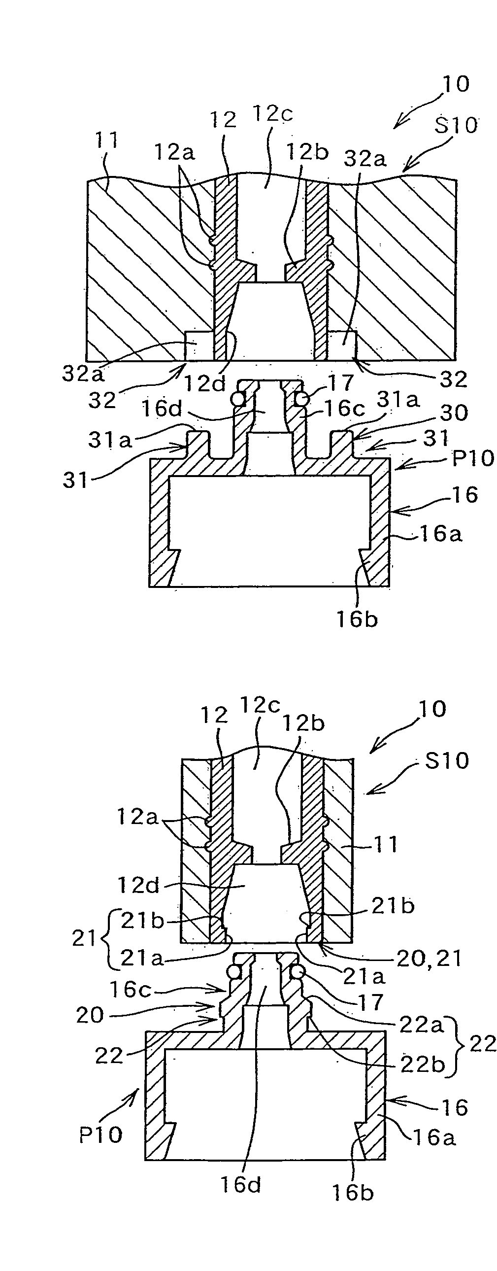
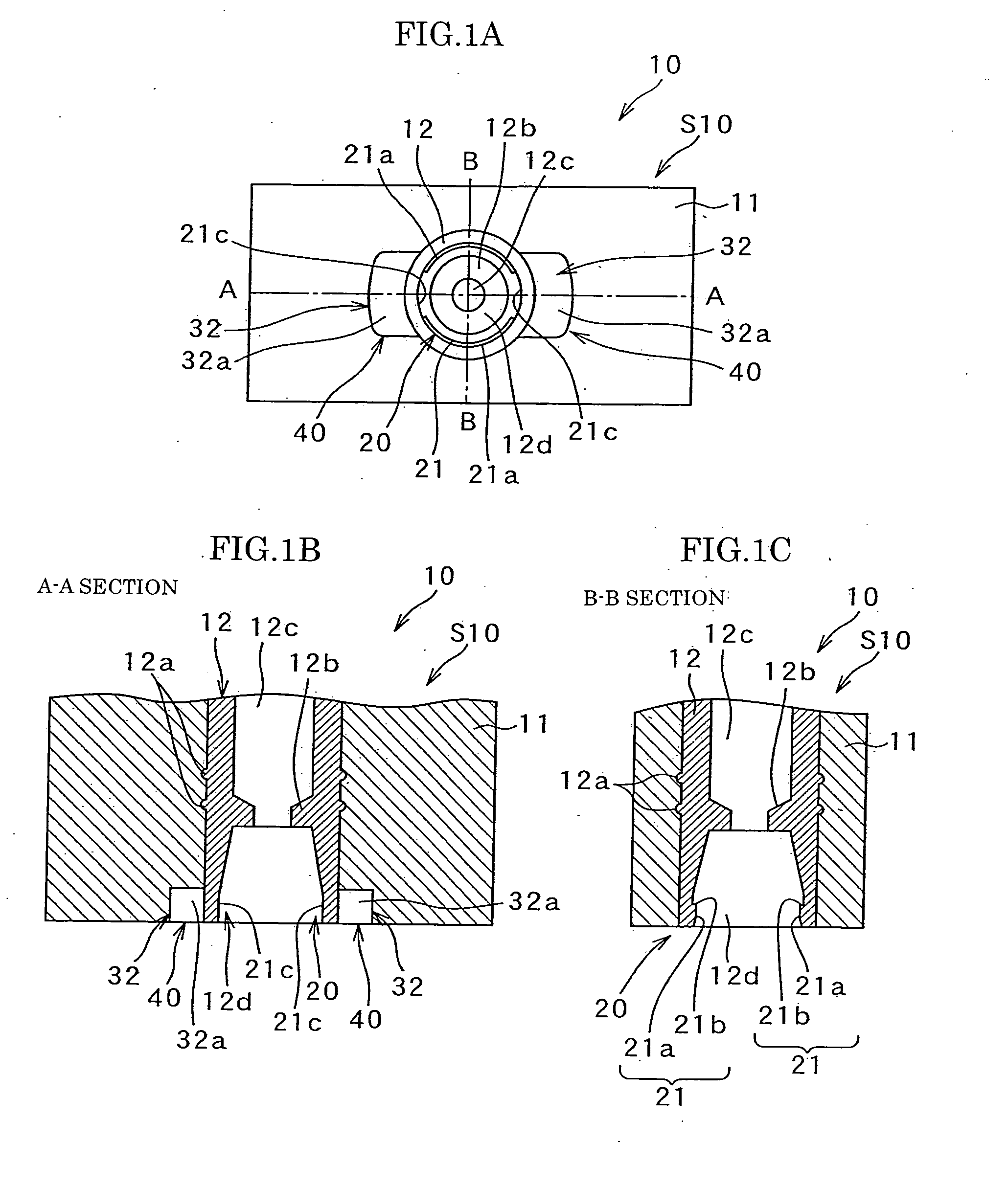
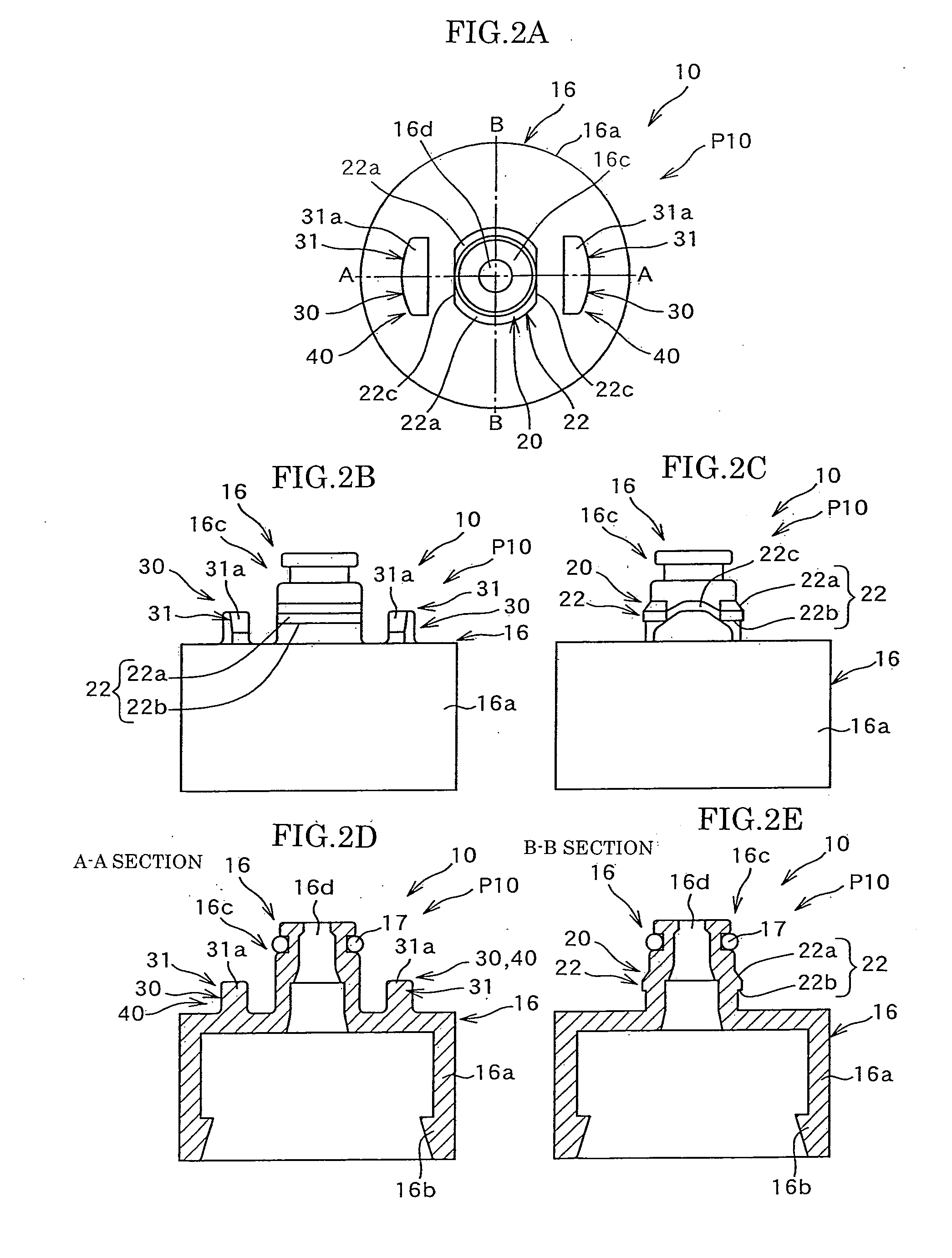
[0118]FIG. 1-4 show an embodiment of the invention in which illustration of a valve and an energizing means therefor of a coupler is omitted. FIG. 1 is a bottom view, a sectional view along lines A-A and a sectional view along lines B-B of a socket, FIG. 2 is a plan view, a front view, a side view, a sectional view along lines A-A and a sectional view along lines B-B of a plug, FIG. 3 is a general perspective view of the plug, and FIG. 4 is a sectional view in the direction of lines A-A and a sectional view in the direction of lines B-B before coupling, and a sectional view in the direction of lines A-A and a sectional view in the direction of lines B-B in a coupling holding state of the coupler.

[0119]This coupler 10 is composed of a socket S10 and a plug P10 which is coupled with the socket S10. The socket S10 is provided on the main body side of, for example, a methanol fuel ...


PUM

PropertyMeasurementUnit
widthaaaaaaaaaa
idling torqueaaaaaaaaaa
rotational forceaaaaaaaaaa

Abstract

As shown in FIG. 4, as coupling holding means 20 for holding coupling between a socket S10 and a plug P10, an engaging projection 22 is formed in the plug P10 and an engaging recess 21 is formed in the socket S10 so that the socket S10 is coupled with the plug P10 accurately by an operation to engage the projection 22 with the recess 21 after an overriding operation of the projection 22. Additionally, on the plug P10 is provided a cam portion 31 which inclines in substantially a circumferential direction about a central axis running in the coupling direction and a cam follower portion 32 is formed in the socket S10. In a case where an abnormal rotational force exceeding a normal range of use is applied, an automatic release of coupling is made between the cam portion and the cam follower portion.

Description

TECHNICAL FIELD[0001]This invention relates to a coupler consisting of a socket and a plug which are detachably coupled to each other and, more particularly, to a coupler of this type by which liquid or other material can be easily and accurately shifted from a container to another container provided on the side of a main body or, alternatively, a container containing such liquid or other material can be exchanged per se by another one and which can be released easily without causing damage when excessive rotational force is applied in the coupled state. This coupler is particularly suitable when it is used as a coupler provided between a cartridge container for a methanol fuel cell and a fuel cell main body.BACKGROUND ART[0002]There are many cases where it is necessary to supplement liquid such as a raw material which decreases by operation or use of an equipment or apparatus. In such cases, supply of liquid such as a raw material is made by coupling a cartridge container to a cont...

Claims


Application Information

Patent Timeline
Patent Type & Authority Applications(United States)
IPC IPC(8): F16L13/14H01M2/00
CPCF16L37/23H01M8/04201Y02E60/50H01M8/1011H01M8/04208Y10T137/87949Y10T137/87957F16L37/32H01M8/04
Inventor YOSHIHIRO, KENJIYAMAMORI, YOUHAYASHI, HIROAKITAKAHASHI, KENICHIKAWAMURA, KOICHI
Owner TOYO SEIKAN GRP HLDG LTD
Why Eureka
Try Eureka