Fly-Eye Lens, Optical Unit and Display Apparatus

Inactive Publication Date: 2009-01-01
SONY CORP
View PDF3 Cites 2 Cited by
  • Summary
  • Abstract
  • Description
  • Claims
  • Application Information

AI Technical Summary

Benefits of technology

[0011]In a case where any one or one at the outermost part of the multiple sub-lenses has an oddly-shaped part, the oddly-shaped part is projected as a result of the image forming by using the sub-lens. The projected oddly-shaped part can be used as a mark for the alignment of the fly-eye lens. Since the light beams collected by the sub-lenses are integrated in a case where an image is formed by using all of the sub-lenses, the effect of the image forming by the oddly-shaped part is at an unrecognizable level.
[0012]According to another embodiments of the invention, there are provided an optical unit and a display apparatus including the fly-ey

Problems solved by technology

However, it is significantly difficult to align the center of the illumination area resulting from the light collection by the fly-eye lens and the center of the display area of a liquid crystal panel, which is an optical modulator.
In other words, it is significantly difficult to determine whether the center of the illumination area and the center o

Method used


Image

  • Fly-Eye Lens, Optical Unit and Display Apparatus
  • Fly-Eye Lens, Optical Unit and Display Apparatus
  • Fly-Eye Lens, Optical Unit and Display Apparatus

Examples


Embodiment Construction

[0019]With reference to drawings, embodiments of the invention will be described below.

[Fly-Eye Lens]

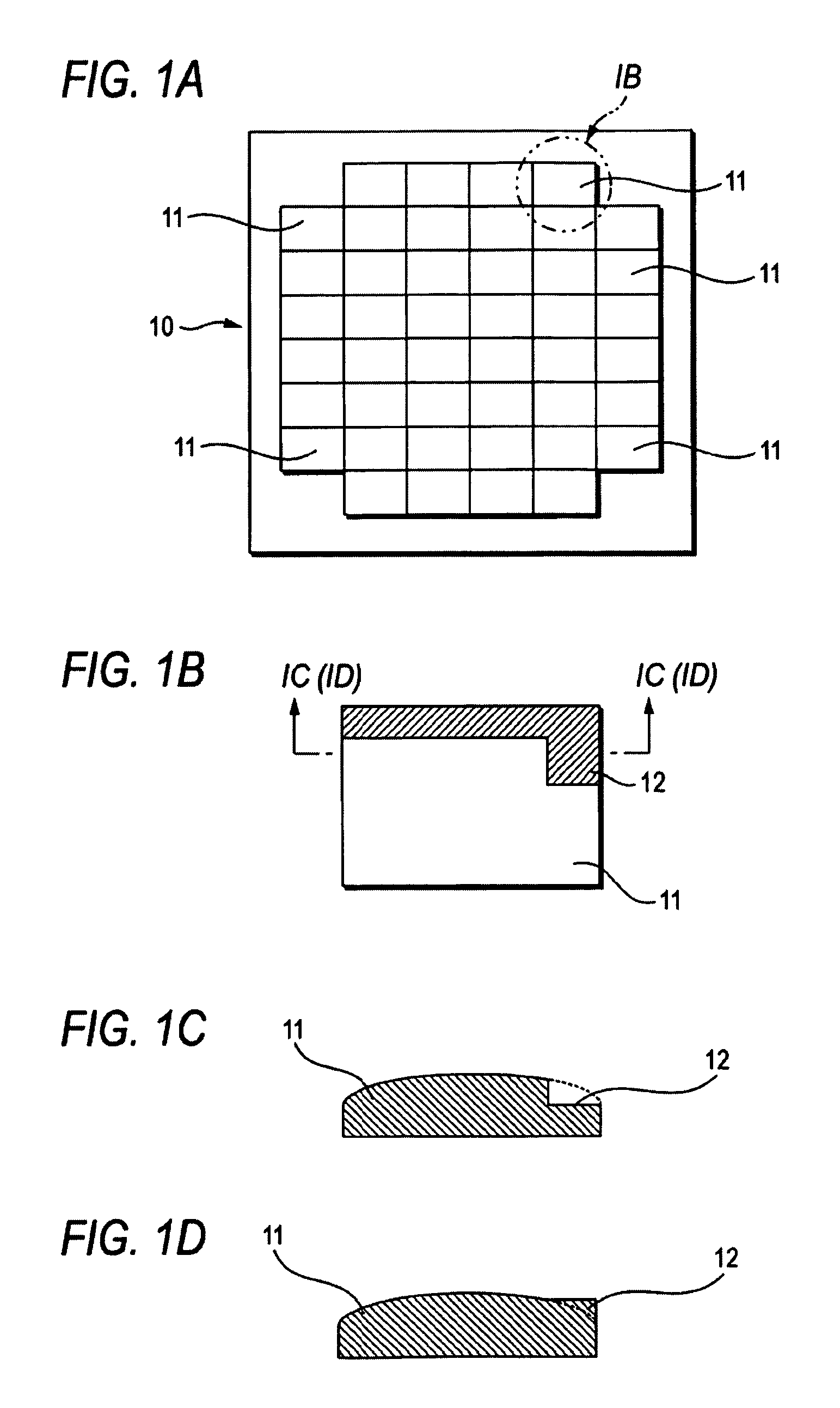
[0020]FIGS. 1A to 1D are schematic diagrams illustrating a fly-eye lens according to an embodiment of the invention. FIG. 1A is a plan view, FIG. 1B is an enlarged view of the part A in FIG. 1A, FIG. 1C is a section view (#1) taken on the line a-a in the Part-A enlarged view in FIG. 1B, and FIG. 1D is a section view (#2) taken on the line a-a in the Part-A enlarged view in FIG. 1B.

[0021]As shown in FIG. 1A, a fly-eye lens 10 according to the embodiment of the invention includes multiple sub-lenses 11 laid out in a matrix form and is an optical integrator that superimposes light beams converged by the sub-lenses 11 to one position.

[0022]The fly-eye lens 10 according to this embodiment is characterized in that a part of the lens surface of any one sub-lens 11 of the multiple sub-lenses 11 has an oddly-shaped part 12 having a different shape from the shape of the lens surfaces of the ot...


PUM


Abstract

A fly-eye lens includes multiple sub-lenses laid out in a matrix form, wherein a part of the lens surface of one sub-lens of the multiple sub-lenses has an oddly-shaped part having a different shape from the shape of the lens surface of the other sub-lenses.

Description

CROSS REFERENCES TO RELATED APPLICATIONS[0001]The present invention contains subject matter related to Japanese Patent Application JP 2007-170148 filed in the Japanese Patent Office on Jun. 28, 2007, the entire contents of which being incorporated herein by reference.BACKGROUND OF THE INVENTION[0002]1. Field of the Invention[0003]The present invention relates to a fly-eye lens including multiple sub-lenses laid out in a matrix form and an optical unit and display apparatus including the fly-eye lens.[0004]2. Description of the Related Art[0005]A projection display apparatus such as a liquid crystal projector divides the light emitted from a light source into three primary color rays of R (red), G (green) and B (blue), guides them to respectively corresponding optical modulators (such as liquid crystal panels) through respective predetermined paths, modulates them and synthesizes them at a synthesis prism, the result of which is then enlarged and projected on a screen through a proje...

Claims


Application Information

Patent Timeline
IPC IPC(8): G03B21/00G02B27/10
CPCG02B3/0043G02B27/0927G02B27/0961H04N9/3197G03B21/00H04N9/3152G02B27/62G03B21/006
Inventor CORN, ROGEROKAMOTO, DAISUKE
Owner SONY CORP
Why Eureka
Try Eureka