Electrochromic device having an improved fill port plug

a technology of electronic devices and fill ports, applied in the field of electronic devices, can solve the problems of inoperable devices, substantial damage to the interior, and compromise the longevity and/or functionality of an associated device,

Active Publication Date: 2009-01-01
GENTEX CORP
View PDF100 Cites 14 Cited by
  • Summary
  • Abstract
  • Description
  • Claims
  • Application Information

AI Technical Summary

Benefits of technology

[0016]In yet another preferred embodiment of the present invention, the concentration of the anodic and / or cathodic material preferably ranges from approximately 1 mM to approximately 500 mM, and more preferably from approximately 2 mM to approximately 100 mM.

Problems solved by technology

Although such fill port plugs have been readily utilized, issues relative to plug compatibility, curability and / or reliability remain paramount to the commercialized success of electrochromic devices such as, for example, electrochromic mirrors, electrochromic windows, and electrochromic aircraft transparencies.
Indeed, incomplete plug curing and / or failure can not only render an associated electrochromic device inoperable, but leakage of the electrochromic medium contained within the electrochromic device can also substantially damage the interior of, for example, an automobile, building, and / or aircraft—the owners and / or manufacturers of which can be completely intolerable of such an occurrence.
In addition, gas permeability and / or barrier properties of a plug can compromise the longevity and / or functionality of an associated device.
The uncured plug material that dissolves into the electrochromic media is there for the life of the device and can cause premature device failure.
These failure modes include electrode passivation, instability in UV, visible hazing of the EC media and / or color change.

Method used


Image

  • Electrochromic device having an improved fill port plug
  • Electrochromic device having an improved fill port plug
  • Electrochromic device having an improved fill port plug

Examples


Embodiment Construction

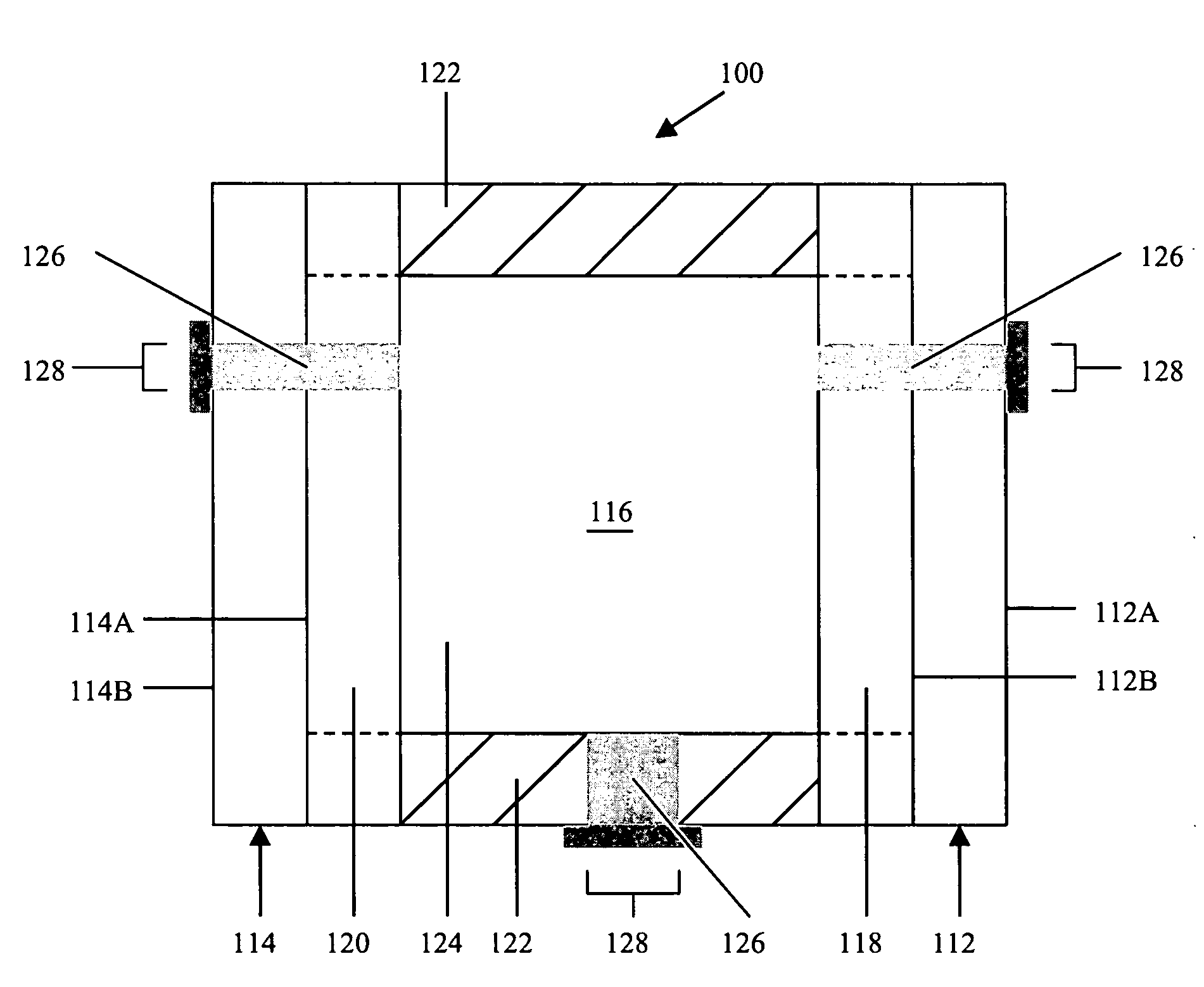
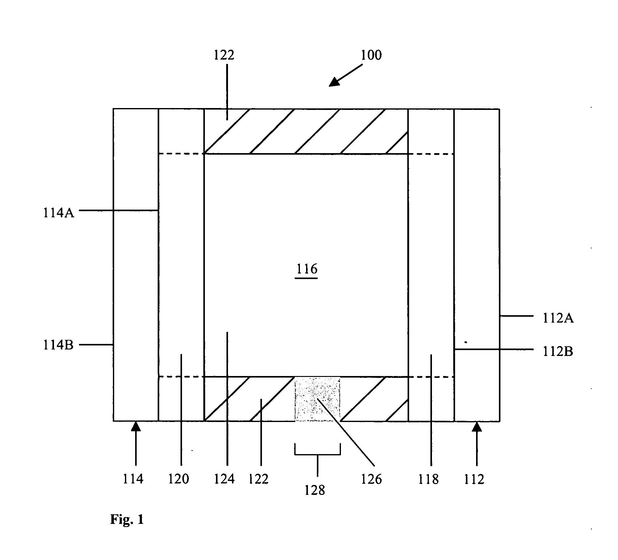
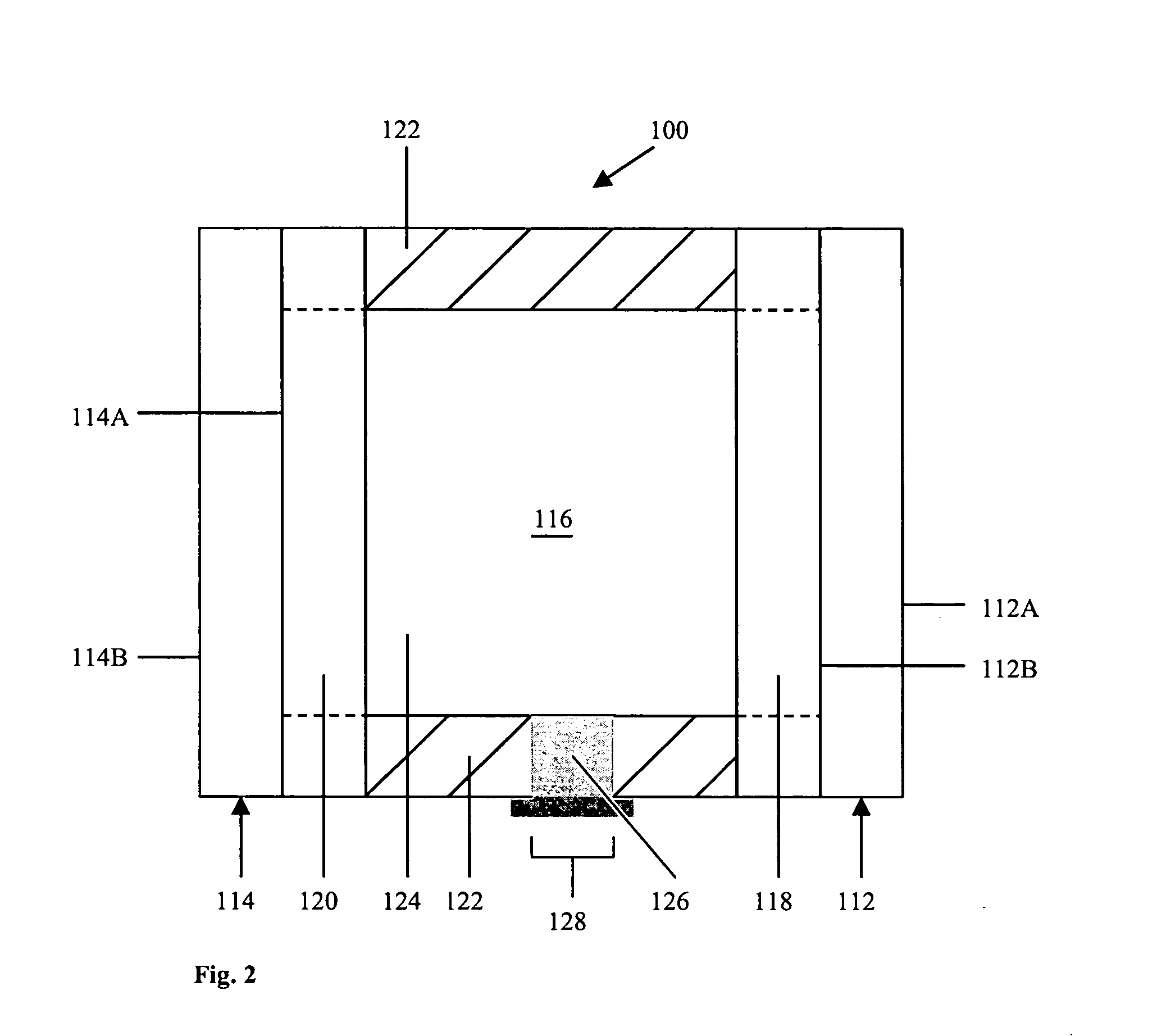
[0032]Referring now to the drawings and to FIGS. 1-7 in particular, cross-sectional schematic representations of electrochromic devices 100 are shown, which generally comprise first substrate 112 having front surface 112A and rear surface 112B, second substrate 114 having front surface 114A and rear surface 114B, chamber 116 for containing electrochromic medium 124, and one or more plugs 126 associated with one or more fill ports 128. In accordance with the present invention, electrochromic devices 100 may comprise, for illustrative purposes only, a window, an aircraft transparency, a mirror, a display device, and the like. It will be understood that like or analogous elements and / or components, and / or methods referred to herein, may be identified throughout the drawings with like reference characters. It will be further understood that FIGS. 1-7 are merely schematic representations of electrochromic devices 100. As such, some of the components have been distorted from their actual ...


PUM

PropertyMeasurementUnit
thicknessaaaaaaaaaa
thicknessaaaaaaaaaa
thicknessaaaaaaaaaa

Abstract

An electrochromic device including: (a) a first substantially transparent substrate having an electrically conductive material associated therewith; (b) a second substrate having an electrically conductive material associated therewith; (c) an electrochromic medium contained within a chamber positioned between the first and second substrates which includes: (1) a solvent; (2) an anodic material; and (3) a cathodic material, wherein both of the anodic and cathodic materials are electroactive and at least one of the anodic and cathodic materials is electrochromic; (d) wherein a seal member, the first substrate, the second substrate, and/or the chamber includes a plug associated with a fill port; and (e) wherein the plug is at least partially cured with an antimonate photo initiator and/or is one- or two-part plug which comprises a resin or mixture of resins that are substantially insoluble and/or substantially immiscible with an associated electrochromic medium while in the uncured state.

Description

CROSS-REFERENCE TO RELATED APPLICATION(S)[0001]This application claims the benefit of U.S. Provisional Application No. 60 / 937,354, filed Jun. 27, 2007—which is hereby incorporated herein by reference in its entirety.BACKGROUND OF THE INVENTION[0002]1. Field of the Invention The present invention relates in general to electrochromic devices and, more particularly, to an electrochromic device having a first substrate, a second substrate, a seal member and / or a chamber which comprises a plug associated with a fill port, wherein the plug comprises an antimonate and / or is at least partially cured with an antimonate photo initiator. The present invention further relates to a one- or two-part plug as is disclosed herein, wherein the plug comprises a resin or mixture of resins that are substantially insoluble and / or substantially immiscible with an associated electrochromic medium while in the uncured state.[0003]2. Background Art[0004]Electrochromic (EC) devices have been known in the art ...

Claims


Application Information

Patent Timeline
Patent Type & Authority Applications(United States)
IPC IPC(8): G02F1/161
CPCG02F2202/023G02F1/161
Inventor TONAR, WILLIAM L.STRAY, JOEL A.VEENMAN, STEVEN J.KLOEPPNER, LEROY J.POLL, DAVID L.DOZEMAN, GARY J.MENON, NALINI C.
Owner GENTEX CORP
Why Eureka
Try Eureka