Pixel Array and Tile for a Video Display

a video display and array technology, applied in the field of pixels, can solve the problems of inability to produce pixels individually, inability to automatically mount the pixels, and prohibitive manual mounting costs

Inactive Publication Date: 2009-01-01
MICHAEL ROBERT
View PDF8 Cites 4 Cited by
  • Summary
  • Abstract
  • Description
  • Claims
  • Application Information

AI Technical Summary

Benefits of technology

[0007]In the present invention, a different approach is taken to forming pixel arrays. With the present invention, a pixel array can be formed in two parts. A reflector array for the pixels in the array represents one part and a carrier for the dice, capable of locating the dice relative to the reflector array, represents the second part. Optionally, pegs may be included to allow precise positioning of pixel arrays to form a larger matrix.
[0017]The pixel array of the invention may be used to form a tile in any suitable way. By way of example, each pixel array of the invention may be assembled on a printed circuit board for the tile, using solder balls for connection. This can eliminate the need for “through hole” connection in the tile printed circuit board, which in turn can contribute significantly to reliability of the tile and to that of the ultimate video display.
[0018]It will be appreciated by one skilled in the art that, because the pixel array of the invention may be connected to a printed circuit board carrier without handling individual pixels, pixel topology may be changed much more readily than in the case of the prior art, simply by reworking the printed circuit board. In this way, pixel design may be readily and inexpensively upgraded in accordance with developments in die (LED) performance.
[0027]It will be appreciated by one skilled in the art that the pixel array of the invention can enable practical implementation of a large display matrix, using smaller pixels which can be set at a finer pitch than formerly. This is desirable, because minimum viewing distance of such a display matrix can be reduced and at the same time image quality can be greatly improved.

Problems solved by technology

This could lead to problems in mounting the pixels automatically.
The costs associated with manual mounting were prohibitive.
Problems can be encountered in producing pixels individually and then assembling them into an array.
The problem can be intensified by the fact that there is a desire to make pixels in a smaller form and to pitch them more closely together.
As a result, in practical terms it is extremely difficult to handle pixels individually and to form them into an acceptable array.

Method used


Image

  • Pixel Array and Tile for a Video Display
  • Pixel Array and Tile for a Video Display
  • Pixel Array and Tile for a Video Display

Examples


Embodiment Construction

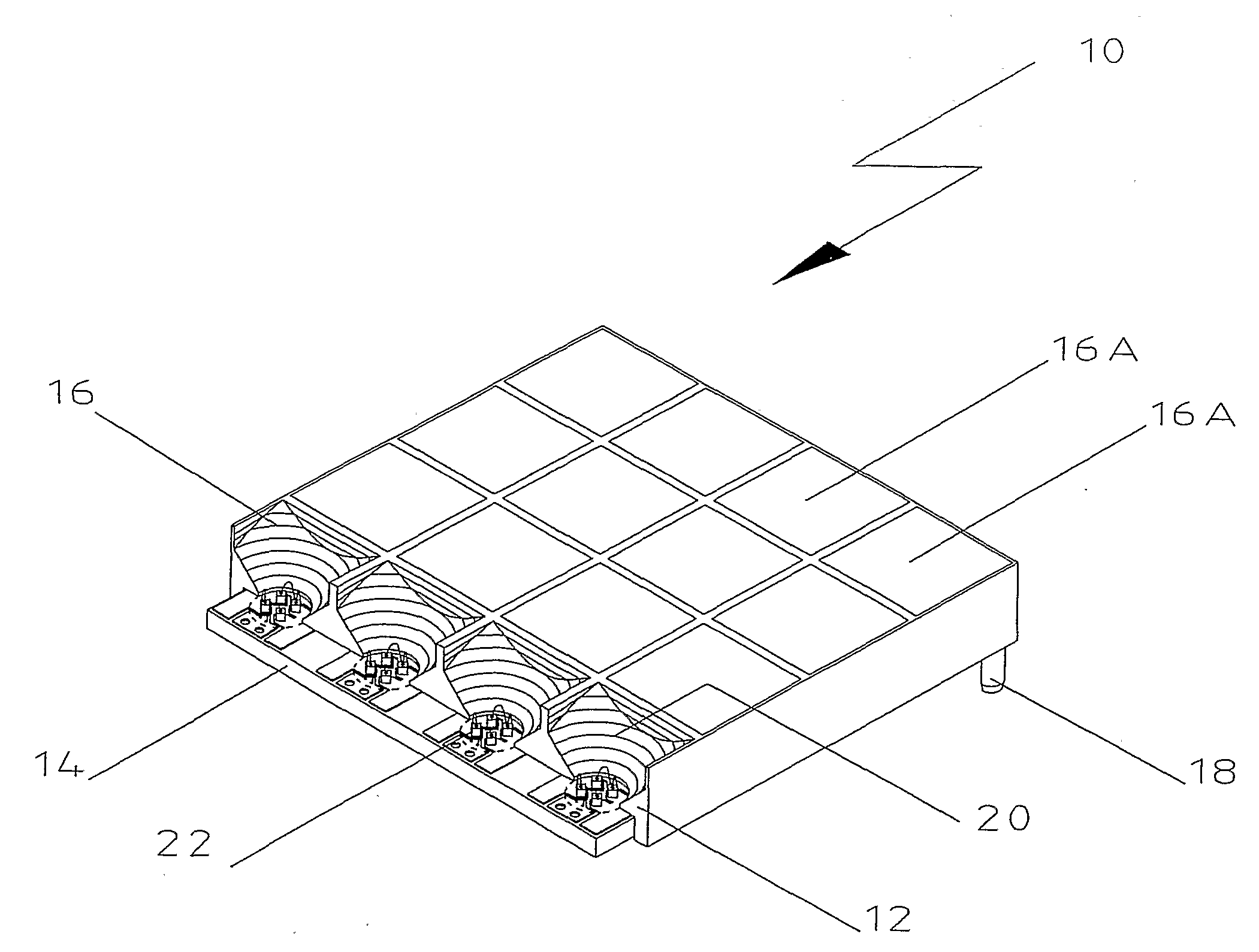
[0041]Turning first to FIG. 1, pixel array 10 is shown with reflector array 12 and dice carrier 14. Pixel array 10 has an array of 4×4 pixels 16, only four of which are shown in detail, in partly broken away form.

[0042]Pixel array 10 includes non-conductive peg 18. Although not shown, a similar peg is located at each of the other three corners of pixel array 10.

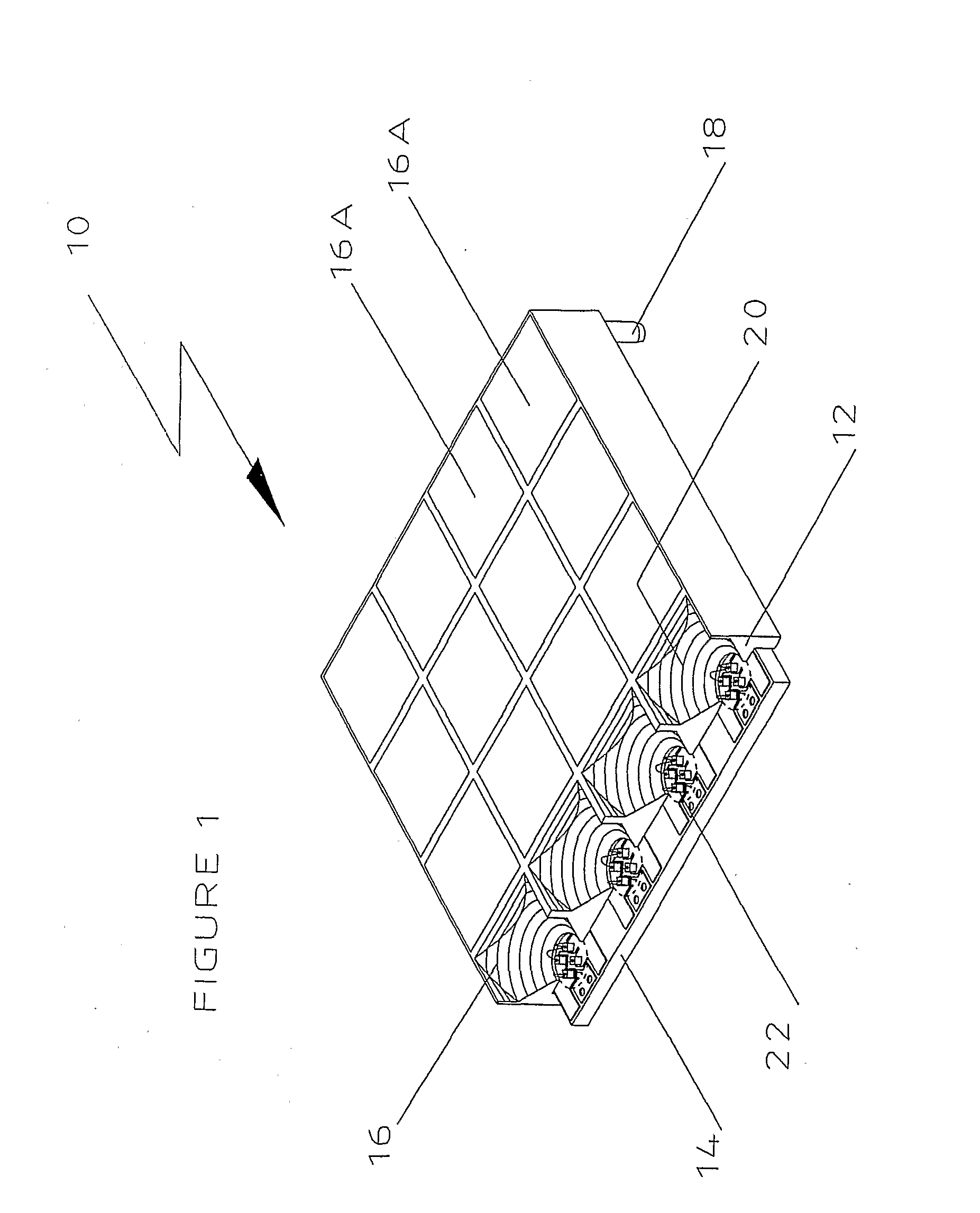
[0043]Reflector array 12 includes sixteen reflector means 20. These are discussed in further detail in connection with FIGS. 2 and 3.

[0044]Pixel array 10 also includes a set of dice for each pixel 16. In this embodiment, each set of dice has four dice, illustrated generally at 22. These may comprise one red die, one blue die and two green dice, or any other desirable combination. The invention is not limited to any particular number of dice, although for colour video displays it is usually necessary to have at least three dice—one red, one blue and one green.

[0045]As can be seen from FIG. 1, each set of dice 22 is situated on...


PUM


Abstract

The invention provides a rectangular pixel array, a tile for a large display such as a video and a method for forming a rectangular array of pixels. The pixel array includes a reflector array having a reflector well for each pixel and a dice carrier including a plurality of dice for each pixel.

Description

TECHNICAL FIELD[0001]This invention relates to pixels, in particular, this invention relates to pixel arrays.BACKGROUND ART[0002]International patent application No WO 94 / 15434 (referred to below as the “International Application”) disclosed a pixel which included light emitting diodes (LEDs) embedded in a light scattering medium and associated with an optical barrier. When this prior art pixel was used to form an array, each pixel was separated from another by an optical barrier.[0003]In an embodiment disclosed in the International Application, the LEDs were mounted to two separate lead frames. To assemble the pixel, jigging was required to hold a reflector for the pixel separately from the lead frame, with both having to be held in a fixed position during curing of the light scattering medium, such as an epoxy resin containing light scattering material.[0004]In one mode of manufacture of the pixels disclosed in the International Application, the pixels which had been formed indivi...

Claims


Application Information

Patent Timeline
Patent Type & Authority Applications(United States)
IPC IPC(8): H01L33/00
CPCG09F9/33
Inventor MICHAEL, ROBERT
Owner MICHAEL ROBERT
Why Eureka
Try Eureka