Eureka AIR delivers breakthrough ideas for toughest innovation challenges, trusted by R&D personnel around the world.

Wire welding and grinding station

a welding and wire technology, applied in the direction of welding devices, soldering devices, manufacturing tools, etc., can solve the problems of large changes in metal structure and welding quality, use of cords creating safety hazards for employees, and the connection from a welding station to a commercial net requires long electrical cords, so as to achieve safe and efficient backup battery movement, the effect of easy movemen

Pending Publication Date: 2020-07-30
NV BEKAERT SA
View PDF0 Cites 0 Cited by
  • Summary
  • Abstract
  • Description
  • Claims
  • Application Information

AI Technical Summary

Benefits of technology

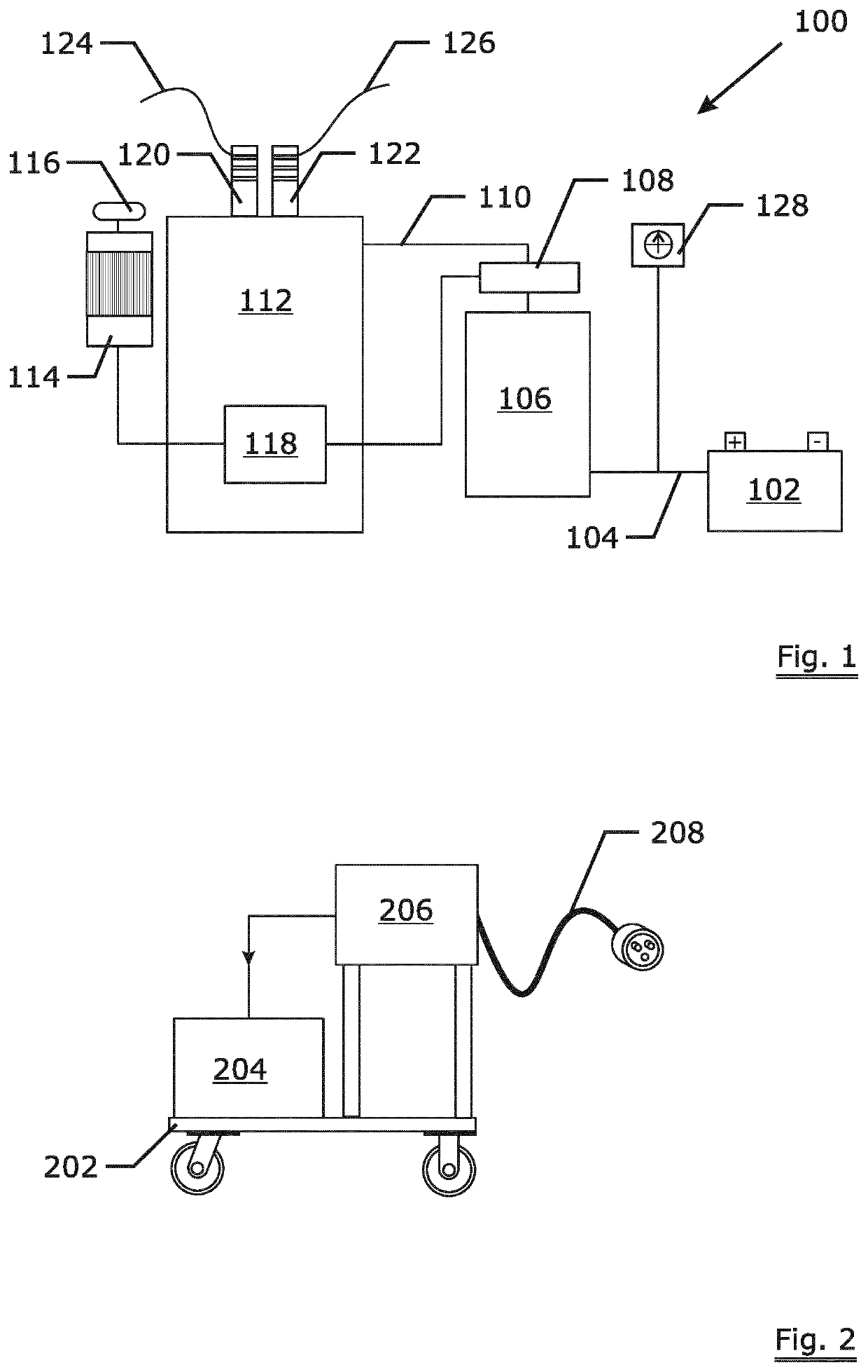
The invention aims to reduce the need for long electrical cords to welding and grinding stations. One solution is to use a portable cart that holds a backup battery and battery charger. This cart can safely and efficiently move the backup battery to a point of power replenishment or from a welding station. The only minimum length of electrical cord needed is to connect the cart to the battery.

Problems solved by technology

Due to the low thermal inertia of wires that causes rapid heating and cooling down, minor parameter changes during welding result in major changes of the metal structure and of the quality of the weld.
Another problem is that connection from a welding station to the commercial net requires long electrical cords.
The use of cords creates safety hazards for the employees since—due to the movability—they cannot be adequately fixed and protected from being a trip hazard or an electrical hazard due to damage or entanglement by processing equipment.
As this AC motor demands a high starting-up current, the so-called inrush current, this AC motor also requires direct connection to the electrical net, which adds other long electrical cords and adds to the complexity of the above-mentioned problem.

Method used


Image

  • Wire welding and grinding station

Examples


Embodiment Construction

[0021]Starting with FIG. 1, a combined welding and grinding station 100 according to the invention has a deep cycle 12 Volt battery 102 that supplies DC current 104 to a 120 Volt power inverter 106. This inverter 106 must be large enough to provide 15 ampere AC needed for providing the desired welds of steel wires. A ground fault circuit interrupter 108 is positioned on the AC connection between the inverter 106 and the rest of the station 100. The inverter provides AC current 110 to the wire welder 112 and the electrical AC motor 114 which drives the grinder 116. The electrical AC motor 114 has a 120 volt soft start module 118 to reduce the inrush current demanded by the electrical AC motor 114 during start-up. The small delay caused by this soft start module 118 has no noticeable impact on the usability. An example of a soft start module would be a Schneider Electric model ATS01N112FT Soft Start Module.

[0022]The wire welder 112 is further equipped with two holding dies 120, 122 ea...


PUM

PropertyMeasurementUnit
diametersaaaaaaaaaa
diameteraaaaaaaaaa
diameteraaaaaaaaaa

Abstract

A wire welding and grinding station (100) comprises a wire welder (112), an AC electrical motor (114) for powering a metal grinder (116), and an AC power supply (110) for supplying electrical power to both the wire welder (112) and the electrical AC motor (114). The station (100) further comprises a soft start module (118) to reduce inrush current demanded by the electrical AC motor (114) while starting. The use of the soft start module (118) allows using a battery (102) as power supply and the use of a battery as power supply has the advantage of practical movability and stable welding currents.

Description

TECHNICAL FIELD[0001]The invention relates to a wire welding and grinding station.BACKGROUND ART[0002]Wire is commonly available or supplied in discrete lengths. Often it is needed to join two lengths wire in order to reach the demanded length or to allow continuity of process.[0003]Joining two lengths of metal wire like steel wire is usually done by welding followed by a grinding operation.[0004]A flat perpendicular face is formed at the end of each length of wire. The ends of wire are aligned, brought together under pressure to upset them and thereafter electrically heated to a welding temperature so that the ends weld together. The pressure is then maintained until the welded material has solidified. Due to the exercised pressure, the diameter may be increased at the welding point. A grinding is then carried out to reduce the diameter to the original value.[0005]Due to the low thermal inertia of wires that causes rapid heating and cooling down, minor parameter changes during weld...

Claims


Application Information

Patent Timeline
Patent Type & Authority Applications(United States)
IPC IPC(8): B23K37/02B23K37/00B23K11/28B23K11/24B23K11/02H02P1/16H02J7/00
CPCH02P1/16H02J7/0047B23K37/0294B23K11/28H02P27/06B23K2101/32B23K11/02B23K37/006B23K11/241B23K11/00B23K11/24B23K28/02B23K37/08B23K11/0026B21F15/08
Inventor SHAW, KURT
Owner NV BEKAERT SA
Why Eureka
Eureka Blog
Learn More