Process cartridge and electrophotographic image forming apparatus

a technology of electrophotographic image and process cartridge, which is applied in the field of process cartridges, can solve problems such as liable damage, and achieve the effect of small siz

Active Publication Date: 2009-01-01
CANON KK
View PDF99 Cites 67 Cited by
  • Summary
  • Abstract
  • Description
  • Claims
  • Application Information

AI Technical Summary

Benefits of technology

[0008]The primary object of the present invention is to provide a process cartridge, the electrophotographic photosensitive drum and development roller of which can be placed in contact with, or separated from, each other, and which is significantly smaller in size than a counterpart in accordance with the prior art, and also, to provide an electrophotographic image forming apparatus in which a process cartridge in accordance with the present invention, is removably mountable.

Problems solved by technology

Therefore, it is liable to be damaged while a user handles a process cartridge, or a process cartridge is conveyed alone.
Further, the presence of the above described force receiving portion has been one of the major problems which arose when studies were made to reduce in size a process cartridge structured so that its electrophotographic photosensitive member and development roller can be placed in contact with, or separated from, each other, and also, when studies were made to reduce in size the main assembly of an image forming apparatus in which such a process cartridge as the one described above is removably mountable.

Method used


Image

  • Process cartridge and electrophotographic image forming apparatus
  • Process cartridge and electrophotographic image forming apparatus
  • Process cartridge and electrophotographic image forming apparatus

Examples


embodiment 1

[0061]Next, referring to FIGS. 1-4, the process cartridges and electrophotographic image forming apparatuses in this preferred embodiment of the present invention will be described.

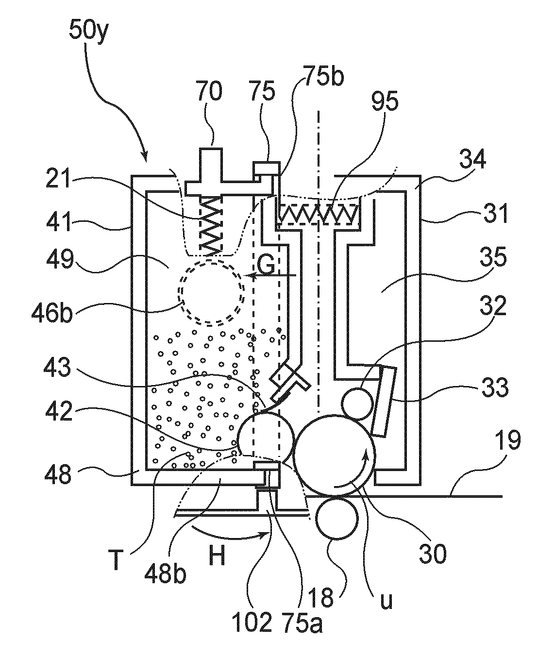
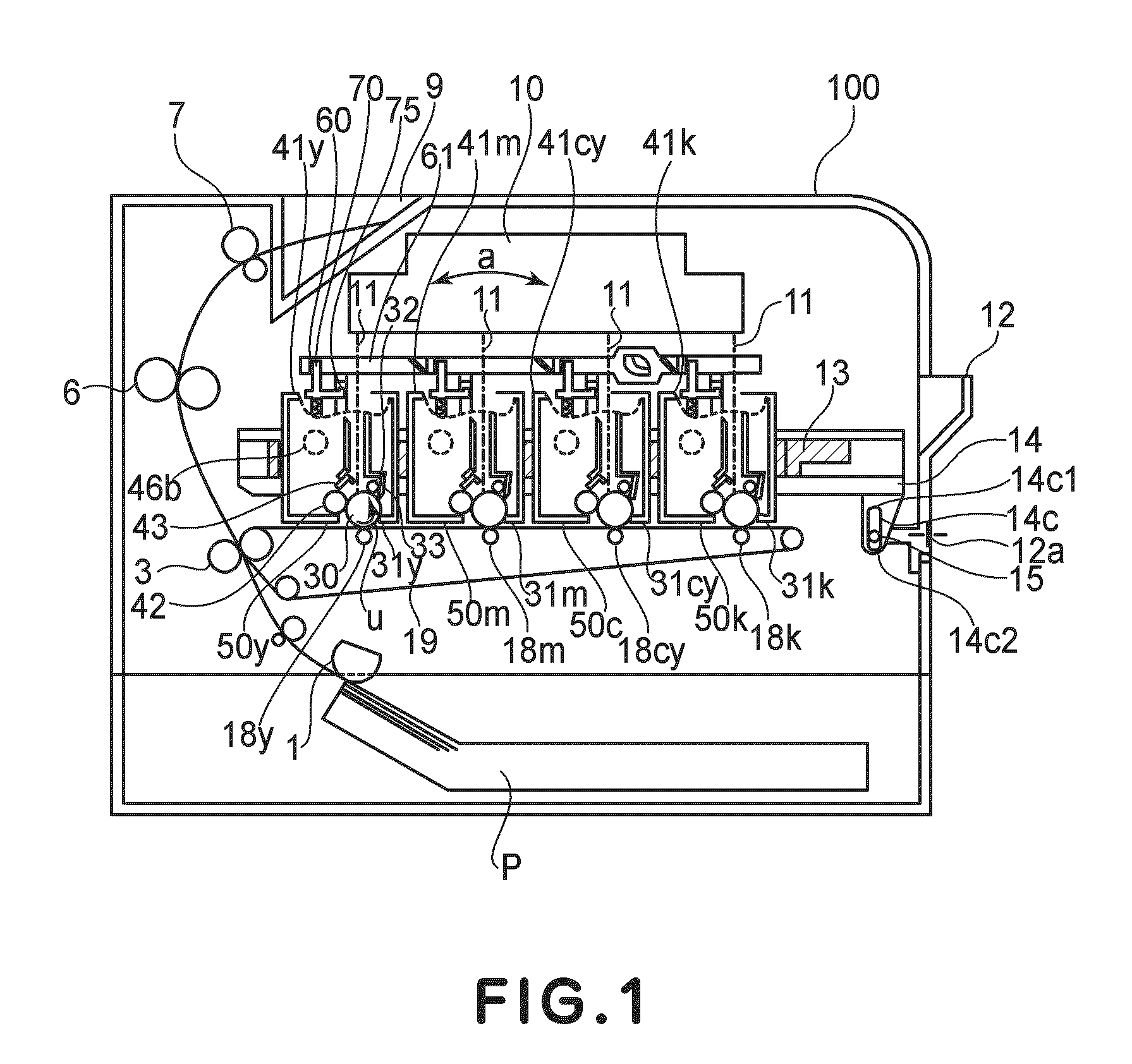
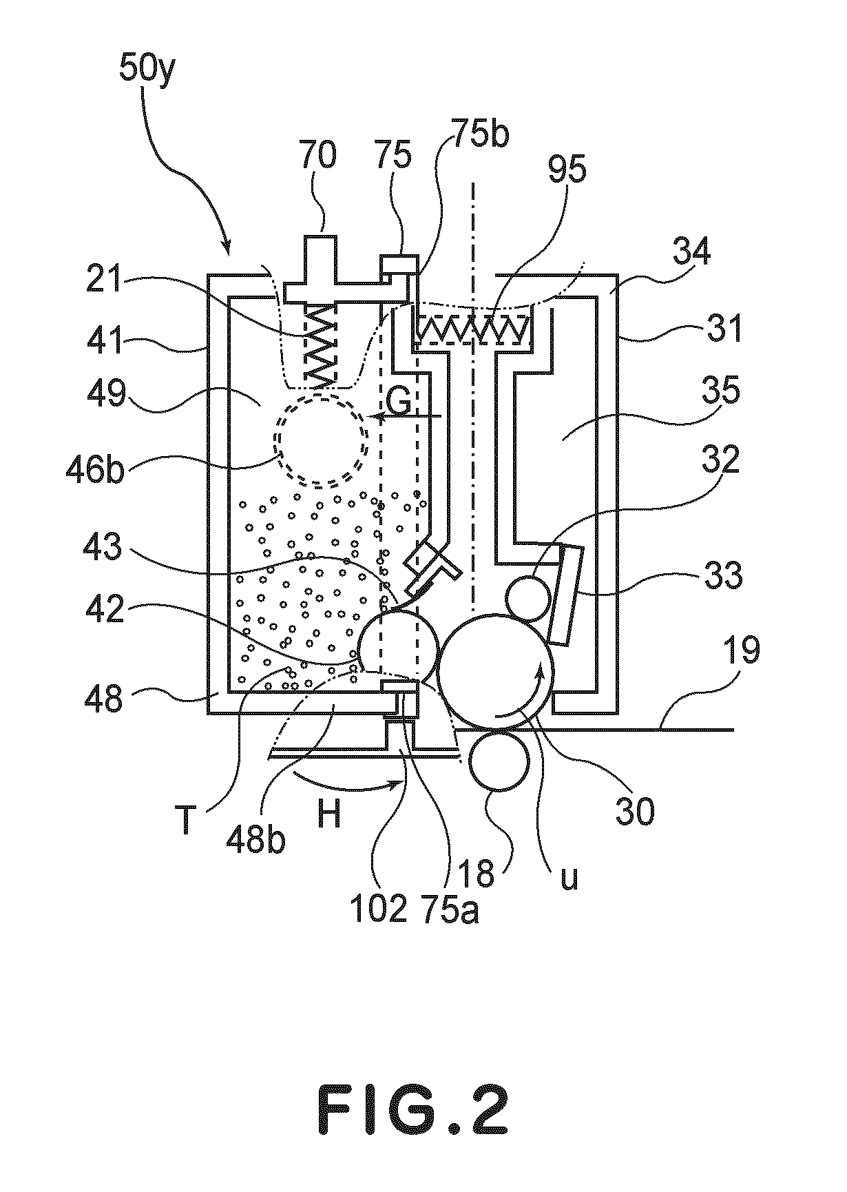
[0062]FIG. 1 is a schematic sectional view of the electrophotographic image forming apparatus 100 (which hereafter will be referred to simply as apparatus main assembly), in which multiple (four) process cartridges 50y, 50m, 50c, and 50k (which hereafter may be referred to simply as cartridges 50) which have been removably mounted. The multiple (four) cartridges 50 store yellow, magenta, cyan, and black toners (developers), one for one. FIG. 2 is a schematic sectional view of the cartridge itself. FIGS. 3 and 4 are schematic sectional drawings of the electrophotographic image forming apparatus in this embodiment, which are for showing how any cartridge or cartridges 50 are removed from the main assembly of the image forming apparatus.

{General Structure of Electrophotographic Image Forming Apparatus}

[0063]...

embodiment 2

[0123]In the first embodiment, the releasing member 75 is disengaged by the projection 102 (releasing member pushing member) solidly attached to the main assembly frame. In this embodiment, however, the cartridge is structured so that the releasing member moves by receiving force from the movable force applying second member, with which the apparatus main assembly is provided.

[0124]This embodiment also will be described with reference to a cartridge, more specifically, a cartridge 950y, which stores the yellow developer. Incidentally, the description of this embodiment will be centered around the structural features of the electrophotographic image forming apparatus in this embodiment, which are different from those in the first embodiment.

{Cartridge Tray of Main Assembly of Electrophotographic Image Forming Apparatus}

[0125]Next, referring to FIGS. 37-39, the operation of the cartridge tray 13 in this embodiment will be described.

[0126]In order to make it easier to understand the op...


PUM


Abstract

A process cartridge detachably mountable to a main assembly of an electrophotographic image forming apparatus, includes an electrophotographic photosensitive drum; developing roller for developing an electrostatic latent image formed on the electrophotographic photosensitive drum; drum frame supporting the electrophotographic photosensitive drum; a developing frame supporting the developing roller, the developing roller being movable relative to the drum frame between a contacting position in which the developing roller is in contact with the electrophotographic photosensitive drum and a spacing position in which the developing roller is spaced from the electrophotographic photosensitive drum; a force receiving member, provided movably relative to the developing frame, for receiving an external force, wherein the force receiving member is capable of taking an operating position for moving the developing frame from the contacting position to the spacing position by receiving the external force, and a stand-by position retracted from the operating position; an urging portion for urging the force receiving member from the stand-by position toward the operating position; and an engaging portion for engaging with the force receiving member to hold the force receiving member in the stand-by position against an urging force of the urging portion.

Description

FIELD OF THE INVENTION AND RELATED ART[0001]The present invention relates to a process cartridge made up of an electrophotographic photosensitive drum and a development roller (which processes photosensitive drum), in particular, a process cartridge, the electrophotographic photosensitive drum and development roller of which can be placed in contact with, or separated from, each other. The present invention also relates to an electrophotographic image forming apparatus employing the above described process cartridge.[0002]In recent years, a process cartridge system has come to be widely used in the field of an image forming apparatus which uses an electrophotographic image forming process. A process cartridge system is one of the electrophotographic image forming systems. It uses a cartridge in which an electrophotographic photosensitive drum, and a development roller, that is, a roller for processing an electrophotographic photosensitive drum, are integrally disposed to make them r...

Claims


Application Information

Patent Timeline
Patent Type & Authority Applications(United States)
IPC IPC(8): G03G21/16G03B30/00G03B17/50
CPCG03G21/1825G03G21/1839G03G21/18G03G21/1842G03G2221/183
Inventor MAESHIMA, HIDEKIMURAYAMA, KAZUNARIYOSHIMURA, AKIRA
Owner CANON KK
Why Eureka
Try Eureka