Magnetic resonance imaging apparatus and magnetic resonance imaging method

a magnetic resonance imaging and magnetic resonance imaging technology, applied in the field of magnetic resonance imaging apparatus and magnetic resonance imaging method, can solve the problems of difficult observation of the blood vessel that is to be diagnosed, difficult from the conventional method to label only the blood vessel to be diagnosed,

Active Publication Date: 2009-01-01
TOSHIBA MEDICAL SYST CORP
View PDF5 Cites 47 Cited by
  • Summary
  • Abstract
  • Description
  • Claims
  • Application Information

AI Technical Summary

Benefits of technology

[0009]The present invention has been made in view of the above-described circumstances, and an object of the present invention is, therefore, to provide a magnet...

Problems solved by technology

When such a portion is included in an imaging region, it is difficult from the conventional method to label only the blood vessel that is to be diagnosed.
For this reason, the time lapse from the labeling to...

Method used


Image

  • Magnetic resonance imaging apparatus and magnetic resonance imaging method
  • Magnetic resonance imaging apparatus and magnetic resonance imaging method
  • Magnetic resonance imaging apparatus and magnetic resonance imaging method

Examples


first embodiment

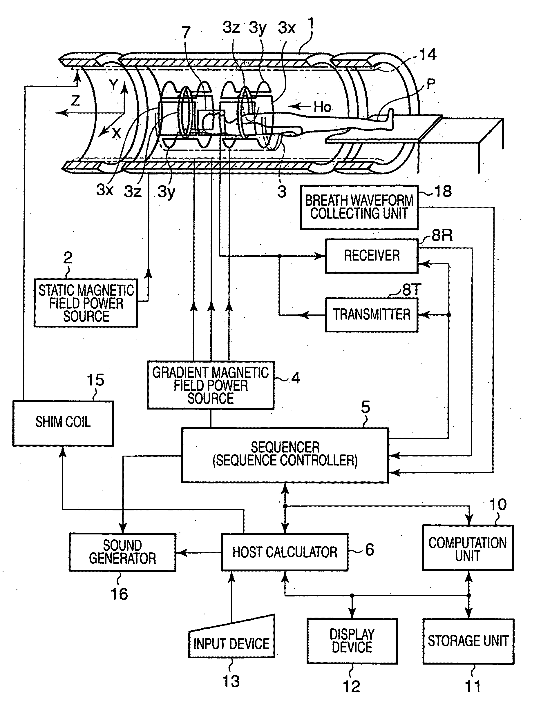
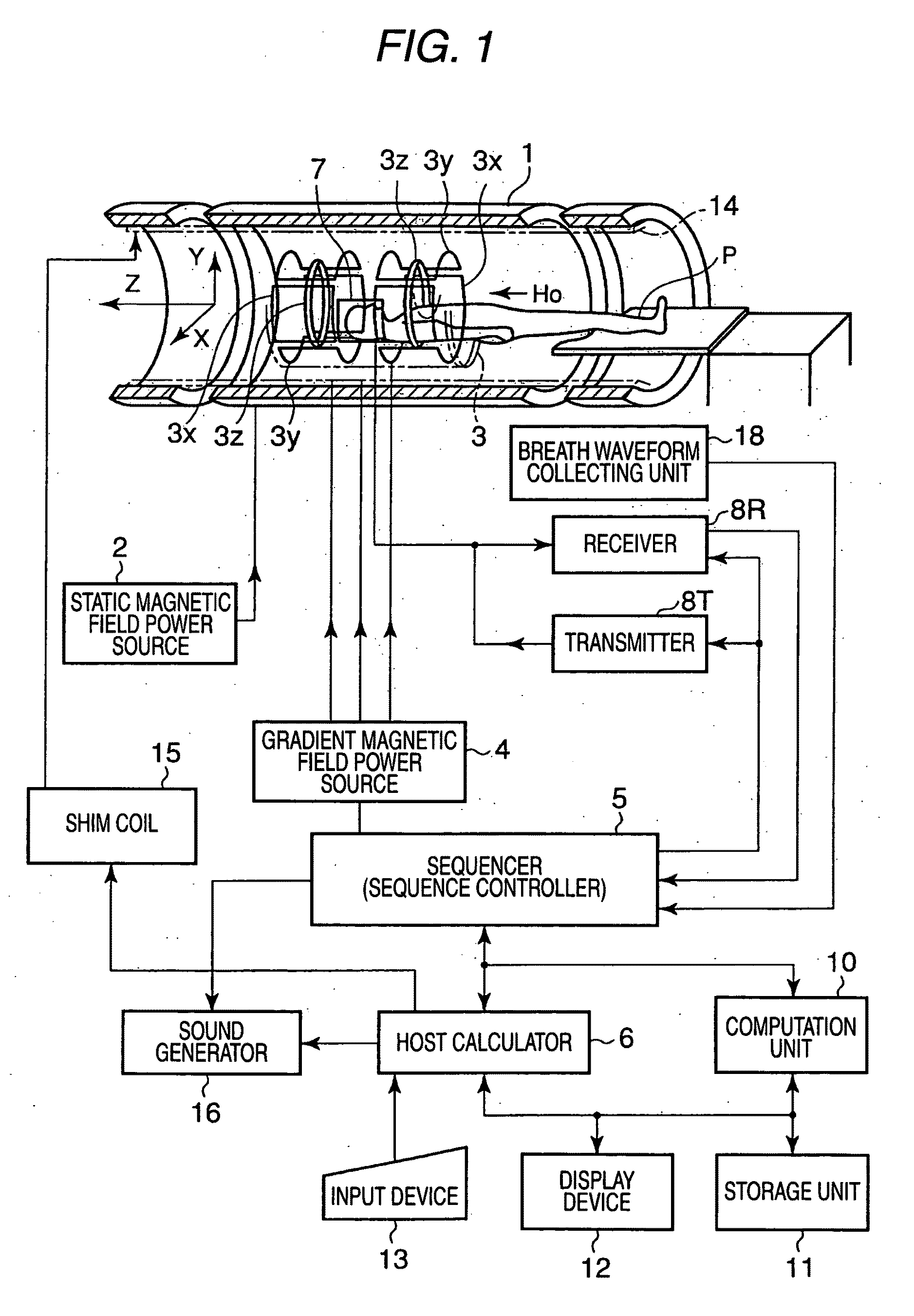
[0032]FIG. 1 is a block diagram showing the configuration of a magnetic resonance imaging apparatus according to a first embodiment of the present invention. As shown in the drawing, the magnetic resonance imaging apparatus includes a bed on which a patient P as a subject lies, a static magnetic field generator for generating a static magnetic field, a gradient magnetic field generator for adding positional information to the static magnetic field, a transmitter / receiver for transmitting / receiving a radio-frequency signal, a control / computation unit that controls the whole system and reconstructs an image, a breath waveform acquisition unit that measures a breath waveform signal as a signal representing the waveform of a breath cycle of the subject P, and a breath-hold instruction unit that instructs the subject P to hold breath.

[0033]The static magnetic field generator includes a superconducting magnet 1 and a static magnetic field power supply 2 for supplying electric current to t...

first application example

Number, Position and Size of Tag Region

[0075]In the non-contrast MRA function of this application example, the number, position, shape, and size of the tag regions are arbitrarily controlled. Therefore, three or more tag regions may be set for one collection of the MR image, and a plurality of tag regions in which the direction or size is different may be set. Moreover, the tag regions may be set such that they overlap with each other.

[0076]FIG. 11 is a diagram showing an example of an MR image obtained by setting a tag region G (TIG=1000 ms) and a tag region H (TIH=990 ms) so as to cross each other. Like this example, when two tag regions are set to cross each other and the time lapses TI of both regions are similar or equal, the overlapping region (crossing region) of the two tag regions is applied twice and substantially simultaneously with the 180-degree inversion pulses (spin excitation pulses); therefore the nuclear spins in the overlapping region will return to their initial ...

second application example

TI Control by Flip Angle

[0078]FIG. 13 is a diagram showing a change with time, of longitudinal magnetization Mz when an IR pulse has a flip angle of 180 degrees. As shown in the drawing, when the flip angle is set to 180 degrees, it takes time of t1 until the longitudinal magnetization Mz becomes zero (Mz=0).

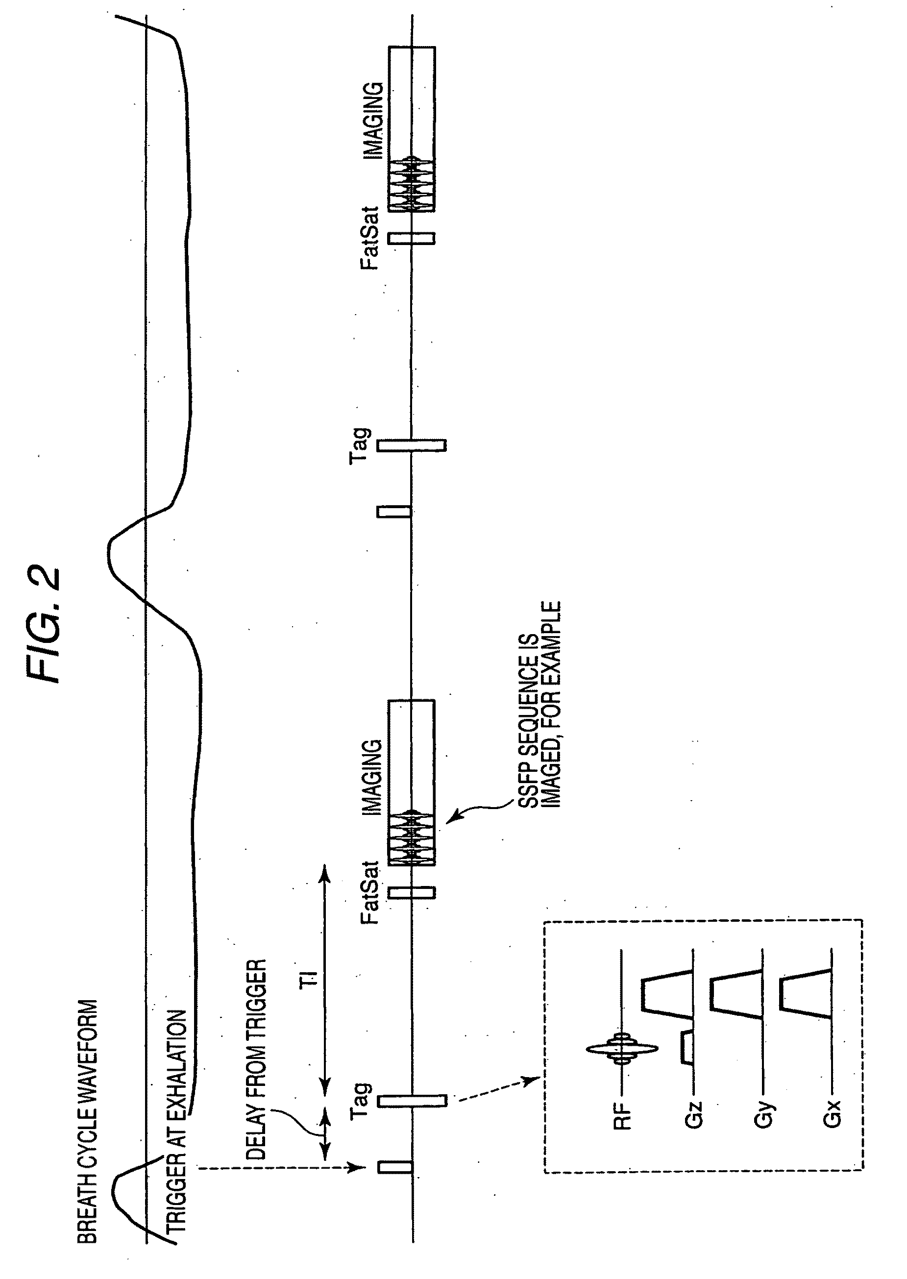
[0079]However, in the case of imaging that uses the breath synchronization method, for example, the imaging sequence is performed after a time lapse TI from a trigger point. For this reason, when the time lapse TI is long, the time difference from the breath synchronization trigger increases, thereby increasing the possibility that the precision of the breath synchronization is lowered.

[0080]To solve such a problem, according to the non-contrast MRA function of this application example, the flip angle θ by the tagging IR pulse is controlled within the range of 90 degrees≦θ≦180 degrees, for example, in order to arbitrarily adjust the time TI at which the longitudinal magnetizatio...


PUM


Abstract

An IR pulse is applied to a tag region B that is disposed at the upstream side of the ascending aorta relative to a tag region A at a timing with a second predetermined delay time TD2 (for example, 600 ms) from the application time of an IR pulse to the tag region A to thereby perform tagging. By this tagging, it is possible to suppress the MR signals derived from the substantial portions and the blood within the tag region B. Subsequently, an imaging scan is performed after a predetermined time lapse TIA (for example, 1200 ms) from the application time of the IR pulse to the tag region A or after a predetermined time lapse TIB (for example, 600 ms) from the application time of the IR pulse to the tag region B.

Description

CROSS-REFERENCE TO RELATED APPLICATIONS[0001]This application is based upon and claims the benefit of priority from prior Japanese Patent Application No. 2007-173204, filed Jun. 29, 2007, the entire contents of which are incorporated herein by reference.BACKGROUND OF THE INVENTION[0002]1. Field of the Invention[0003]The present invention relates to a magnetic resonance imaging apparatus and a magnetic resonance imaging method suited to an observation of the dynamic state of a moving material in a body such as blood or cerebrospinal fluid (CSF).[0004]2. Description of the Related Art[0005]A magnetic resonance imaging apparatus is an apparatus that excites nuclear spins of atoms in a subject magnetically with a radio-frequency signal having the Larmor frequency and acquires an MR signal generated due to the excitation, thereby reconstructing an MRI image or an MRA image (hereinafter, collectively referred to as an MR image).[0006]In recent years, in the art of the magnetic resonance i...

Claims


Application Information

Patent Timeline
IPC IPC(8): A61B5/055
CPCG01R33/5607G01R33/56366G01R33/5635G01R33/56308A61B5/05A61B5/055G01R33/20G01R33/48G01R33/483G01R33/4833G01R33/4835G01R33/4838G01R33/543
Inventor ICHINOSE, NOBUYASUYAMASHITA, YUICHI
Owner TOSHIBA MEDICAL SYST CORP
Why Eureka
Try Eureka