Heart Assist Devices, Systems and Methods

a technology of heart assist and heart device, applied in the field of heart assist device, systems and methods, can solve the problems of slow heart rate, difficult to achieve, complicated implanting, maintaining and removing, etc., and achieve the effect of improving blood circulation

Inactive Publication Date: 2008-06-12
NUWELLIS INC
View PDF30 Cites 48 Cited by
  • Summary
  • Abstract
  • Description
  • Claims
  • Application Information

AI Technical Summary

Benefits of technology

[0026]b) a flexible, substantially inelastic, sheath adapted to extend around the cuff and at least assist in retaining it in position on the aorta.
[0068]The system and device of the invention allow relief / recovery from chronic heart failure whilst allowing the subject to move around freely without being constrained by a large external pumping device.

Problems solved by technology

LVADs pump blood and significantly improve life style and survival, but are complicated to implant, maintain and remove, with relatively high complications relating to bleeding, infection, thromboembolism, and device malfunction.
The transplant rate has stabilised at approximately 2,300 per year in the USA, being limited by organ availability.
However, the balloon comes into direct contact with the blood flowing into the aorta, which can cause damage to the blood cells and there is a risk of thromboembolism.
The tube is typically inserted into a groin vessel, the femoral artery, and there is a high risk of associated leg complications.
Further, the patient is bedridden and cannot mobilize.
Additionally, the use of a gas to inflate the balloon is not an entirely safe operation since any leakage of gas from the balloon into the blood stream could cause an air embolus.
Although this device has advantages for many applications, it does require relatively complicated surgery to implant / explant the device, particularly in regard to the need to mount the device including its motive means, to the ribs of the patient.
Moreover the mounting arrangement and motive means of the device have to be positioned outside the rib cage, making the presence of the device more noticeable to the patient.
There is also substantial risk of infection With the device coming through the skin.
Furthermore, because the device is attached / mounted to the ribs, there may be shear stresses on the aorta as the rib cage moves with inspiration / expiration.
These stresses may cause untoward damage of the aorta.
Although this approach may be useful in some circumstances, it is doubtful that it is suitable for long term in that the muscle function would probably degrade over time.
Furthermore, the muscle has to be “trained” for many weeks before the device can be relied on to assist blood circulation.
A disadvantage of the disclosed device is it has a separate actuator and compliance chamber and its implantation is thus complicated.
Another disadvantage is it is difficult to securely mount the device components to a structure in the abdominal cavity that is capable of supporting its weight.
A further disadvantage is a number of vertebral arteries stem from the descending aorta which can be damaged during the implantation of the device.
In a small proportion of patients however there will exist aortic disease making a periaortic device unsuitable.

Method used


Image

  • Heart Assist Devices, Systems and Methods
  • Heart Assist Devices, Systems and Methods
  • Heart Assist Devices, Systems and Methods

Examples


first embodiment

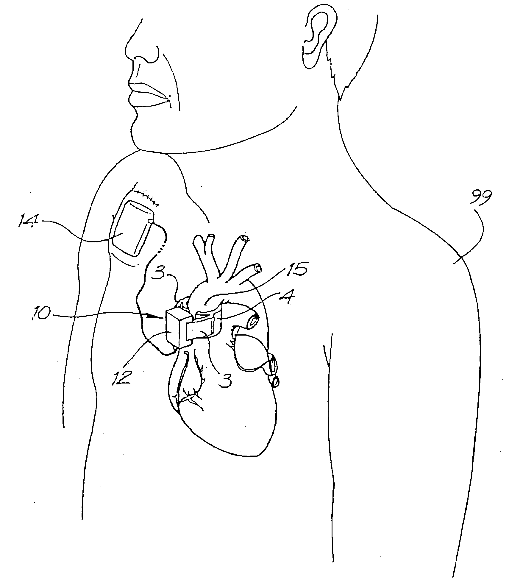
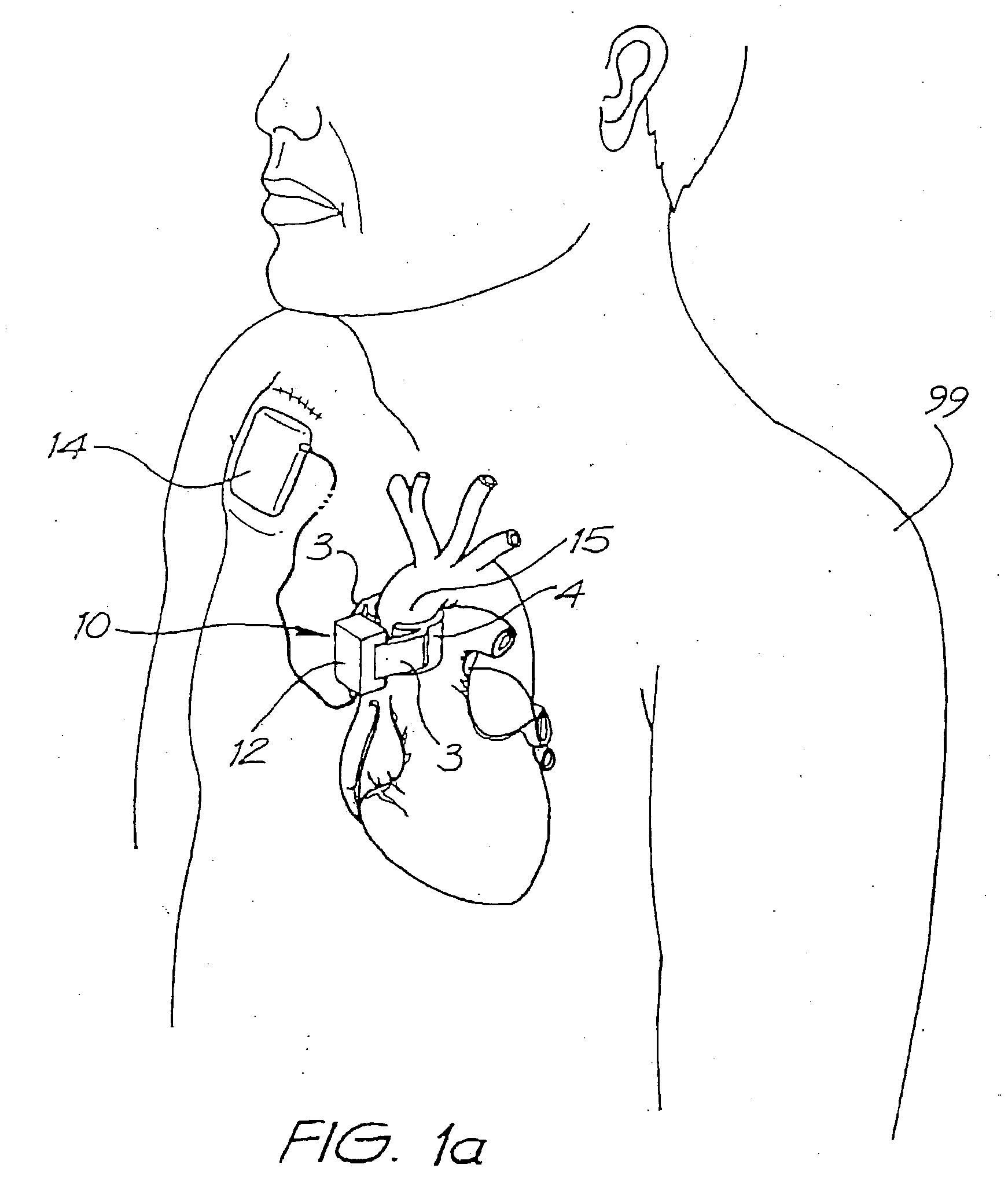
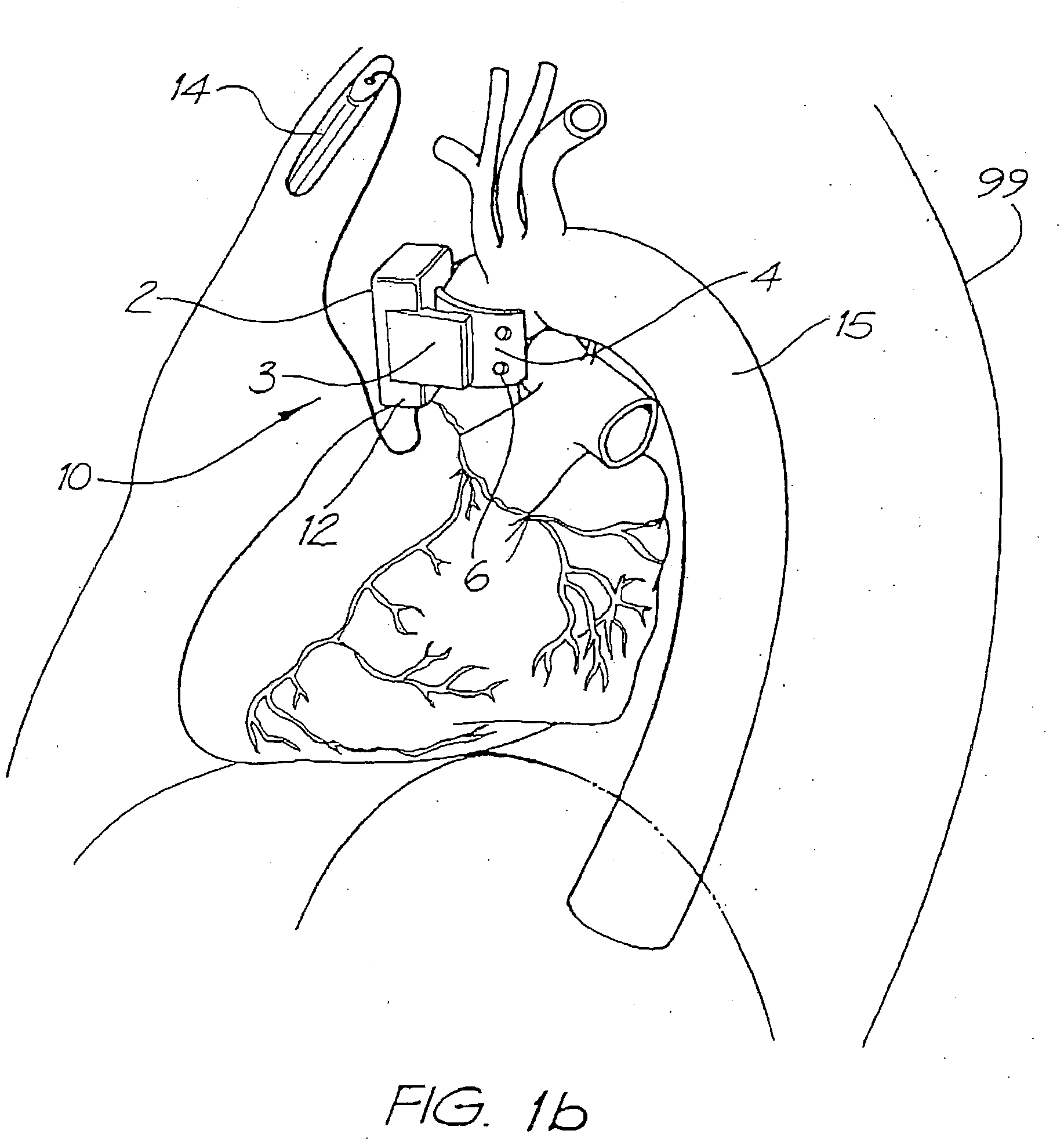
[0092]FIG. 1a to 2b are schematic drawings showings a heart assist device 10 in accordance with the invention. The device 10 is suitable for complete implantation in the thoracic cavity of a subject 99 adjacent the ascending portion of the aorta 15, as shown. The device 10 includes an aortic compression means in the form of a hinged solenoid 2 (see FIGS. 2a and 2b) in a housing 12. The solenoid 2 is driven by pulses of electrical power from a controller / battery 14 to actuate wedge-shaped compression plates 4 via arms 3. The wedge-shaped plates 4 surround the ascending portion of the aorta 15. When the plates 4 are actuated they approach each other and that part of the aorta 15 between the plates 4 is compressed. The plates 4 have a plurality of holes 6 that provide means for suturing the plates to the aorta 15 and permitting ingrowth of tissue therethrough.

[0093]FIGS. 2a and 2b are detailed schematic drawings of the solenoid 2 which show that it includes two arcuate plates 26 hinged...

second embodiment

[0095]In the second embodiment shown in FIG. 3, the compression plates 34 are actuated via arms 33, with each of the arms 33 being acted on by a respective rod solenoid 38 acting through springs 37 between the rod solenoid 38 and the respective arm 33.

third embodiment

[0096]In the third embodiment shown in FIG. 4, solenoids 48 act on deformable nitinol plates 44 connected together at either end 47 to encircle the aorta 15.


PUM


Abstract

An apparatus and method for use in assisting a human heart are disclosed. The apparatus comprises an aortic compression means which may be fully implanatable, a fluid reservoir and a pump means adapted to pump a fluid from the reservoir to the aortic compression means so as to actuate the aortic compression means at least partly in counterpulsation with the patient's heart. In addition, the device is adapted to be wholly positioned within the right chest cavity of the patient. The aortic compression means of the device may be curved along its length so as to substantially replicate the curve of the ascending aorta.

Description

RELATED INFORMATION[0001]This application is a continuation of co-pending application Ser. No. 10 / 786,699 filed on Feb. 24, 2004, which is a continuation of U.S. application Ser. No. 09 / 869,923 filed on Oct. 15, 2001. The priority of the prior application is expressly claimed, and the disclosure of this application is hereby incorporated by reference in its entirety.FIELD OF THE INVENTION[0002]The present invention relates to heart assist devices, systems and methods.BACKGROUND OF THE INVENTION[0003]Currently the only real options for improvement of end-stage heart failure are medical therapy, left ventricular assist devices (LVADs) and transplantation. ACE (Angiotensin Converting Enzyme) inhibitors unload the heart and prolong survival. LVADs pump blood and significantly improve life style and survival, but are complicated to implant, maintain and remove, with relatively high complications relating to bleeding, infection, thromboembolism, and device malfunction.[0004]The transplant...

Claims


Application Information

Patent Timeline
Patent Type & Authority Applications(United States)
IPC IPC(8): A61M1/12A61M1/10
CPCA61M1/1037A61M1/106A61M1/1067A61M1/107A61M1/12A61M1/122A61M2230/30A61M1/1051A61M1/1055A61M1/1063A61M1/1065A61M2230/04A61M60/432A61M60/435A61M60/274A61M60/148A61M60/161A61M60/289A61M60/481A61M60/478
Inventor PETERS, WILLIAM SUTTLEMARSH, PETER CRISPIN LAWRENCEWHITE, GEOFFREY HAMILTONUNGER, ROLF GUNNARMILSOM, FREDERICK PAGETHENRICHSEN, HANS HANSFORTHSULLIVAN, COLIN EDWARD
Owner NUWELLIS INC
Why Eureka
Try Eureka