Method and apparatus for percutaneous aortic valve replacement

a technology of aortic valve and percutaneous insertion, which is applied in the field of medical procedures and devices, can solve the problems of increasing the difficulty of precise placement of the pav, increasing the risk of device embolization, and affecting the safety of patients, so as to promote patient stability, promote continuous coronary perfusion, and minimize the stress of the cardiac muscl

Active Publication Date: 2009-01-29
HOCOR CARDIOVASCULAR TECH
View PDF62 Cites 57 Cited by
  • Summary
  • Abstract
  • Description
  • Claims
  • Application Information

AI Technical Summary

Benefits of technology

[0008]Salient features of the PAV delivery and deployment system of the present invention are the capability to (1) achieve an adequately stable physiologic and anatomic environment for device positioning and deployment, and (2) maintain sustainable hemodynamic conditions allowing for the completion of the procedure without undue patient instability. To achieve a stable environment for both the PAV implantation and patient safety, a temporary “aortic valve” is introduced into the ascending aorta. To simplify the local anatomy allowing for a relative unobstructed PAV placement, pre-dilation and ablation of the native aortic valve precedes PAV delivery and deployment.
[0010]Once inflated, the TAV functions as a valve allowing limited blood flow in a forward direction, up through the coronary arteries and ascending aorta during systole. During diastole, the TAV functions to limit backflow into the left ventricle while still allowing continued perfusion in the coronary arteries.
[0011]The TAV promotes patient stability during the PAV replacement procedure in at least two ways. First, use of the TAV promotes continuous coronary perfusion during native valve ablation and replacement. Second, use of the TAV in place of the ablated native stenotic aortic valve minimizes the stress encountered by the cardiac muscle due to partial alleviation of the transvalvular pressure gradient.
[0012]In addition, the contiguous design of the TAV with central catheter provides a reliable vehicle demonstrating structural integrity for the delivery and deployment of the PAV device and related procedural tools.

Problems solved by technology

In the PAV replacement procedure, most of the cardiac complications occur at the required precise placement of the PAV during implantation.
Due to the aortic valve's close proximity to the coronary ostia on one side, and the mitral valve on the other, misalignment of the PAV can cause serious compromise of coronary or mitral valve function [Boudjemline Y, et al., Circulation 2002;105(6):775; Ferrari M, et al., Heart 2004;90(11):1326-1331].
The significant hemodynamic forces encountered at the left ventricular outflow tract to the ascending aorta, together with the anatomic structures comprising the native valve, add to the difficulty of precise placement of the PAV and the risk of device embolization.

Method used


Image

  • Method and apparatus for percutaneous aortic valve replacement
  • Method and apparatus for percutaneous aortic valve replacement
  • Method and apparatus for percutaneous aortic valve replacement

Examples


Embodiment Construction

Temporary Aortic Valve

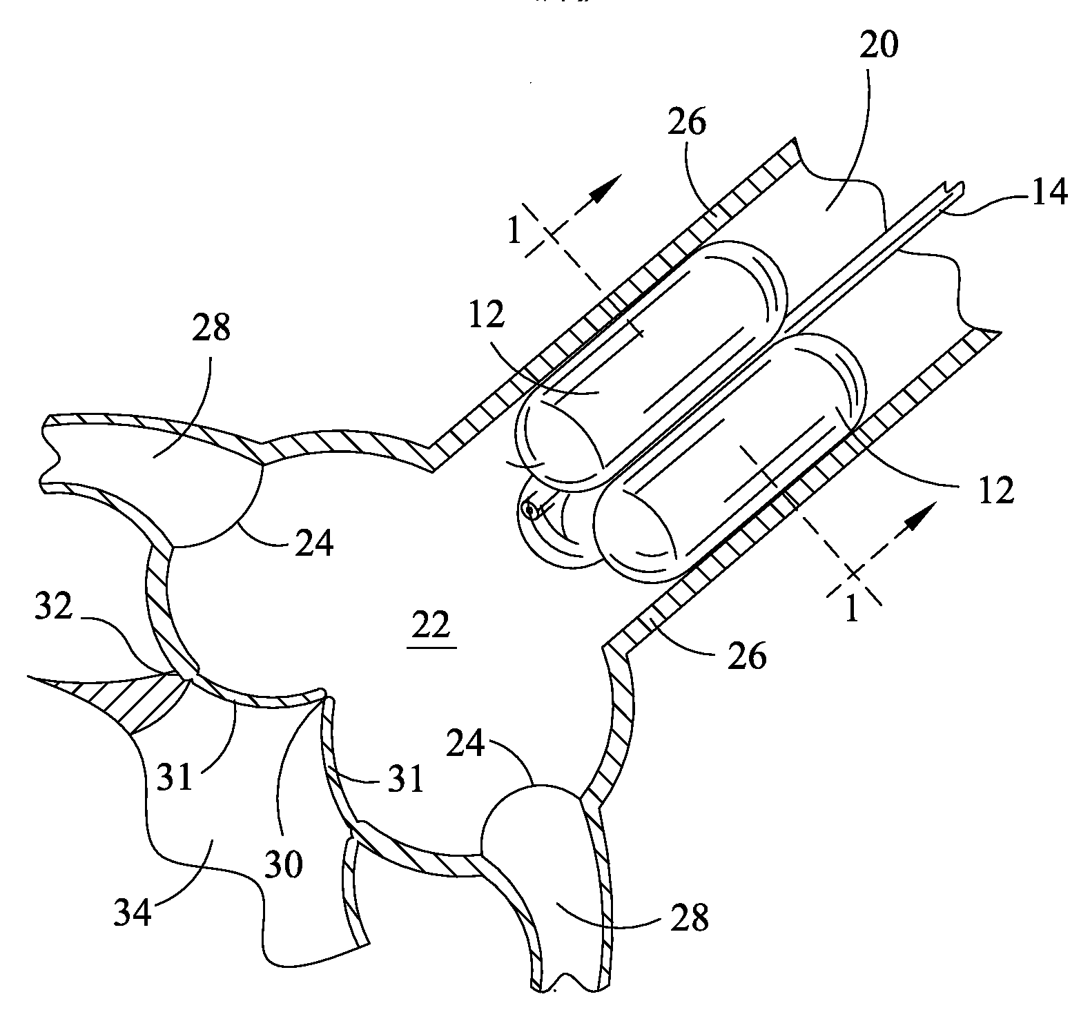
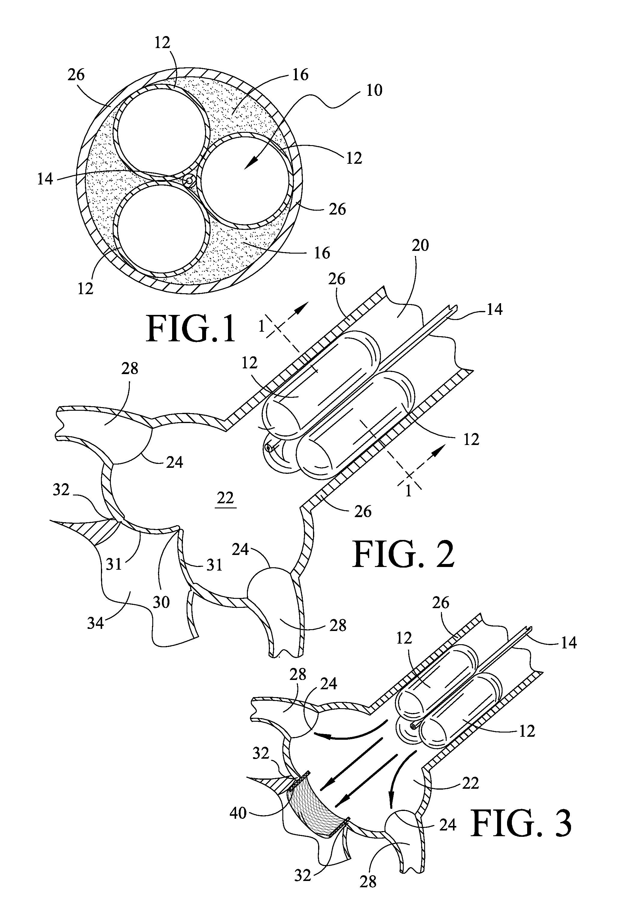
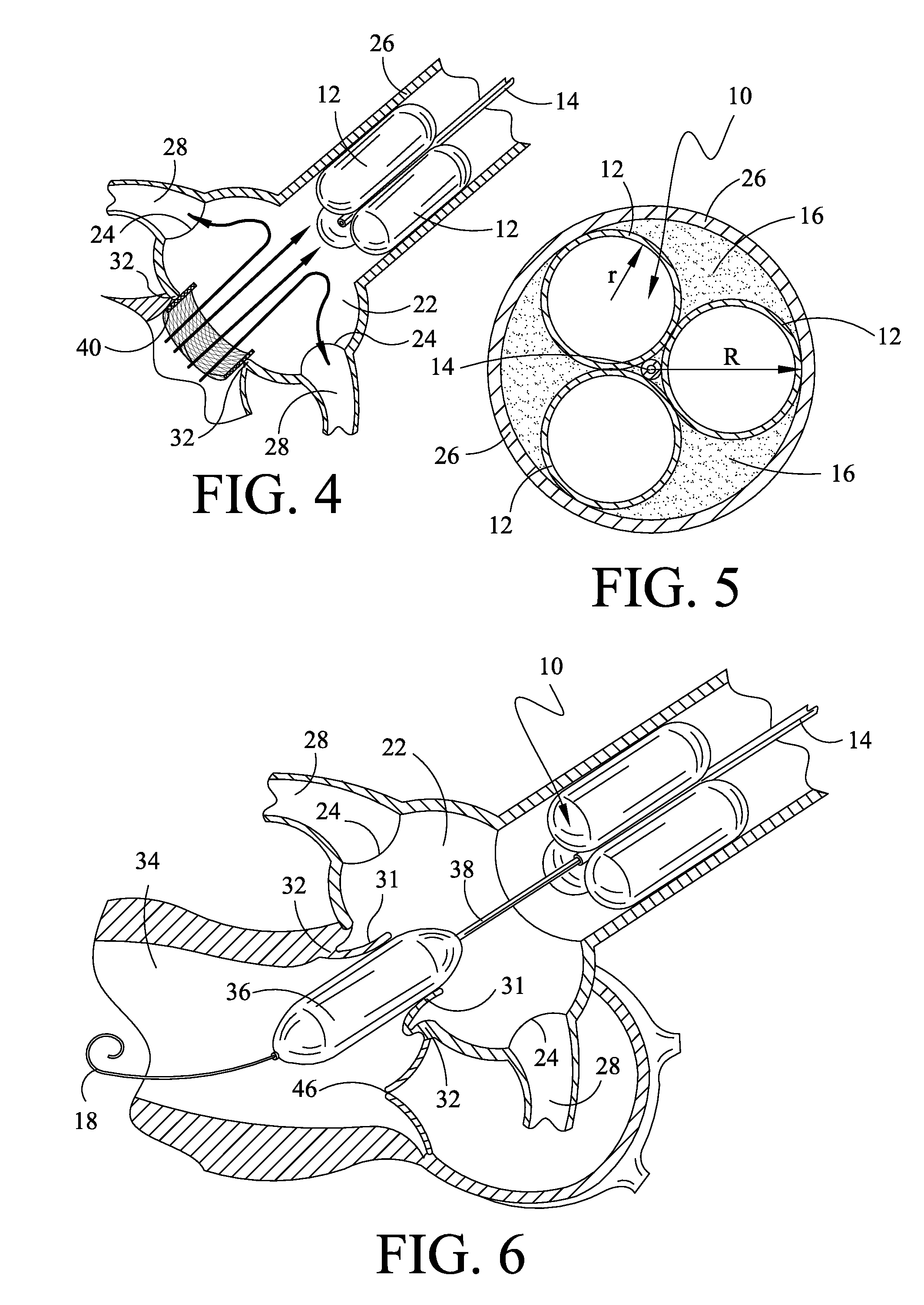
[0024]Illustrated in FIG. 1 in cross section and FIG. 2 in side view is the temporary aortic valve (TAV) 10 of the present invention. According to the preferred embodiment shown, TAV 10 is comprised of three elongated supporting-balloons 12 of equal shape and size, contiguously arranged in parallel around a central guiding-catheter mechanism 14.

[0025]TAV 10 is placed within the ascending aorta 20 by means of catheter 14, and then inflated. FIG. 2 depicts TAV 10 deployed to a position within ascending aortic 20 just above (downstream from) the Sinus of Valsalva 22 and the coronary ostia 24. Once in position, supporting balloons 12 are inflated such that TAV 10 is lodged firmly against the inside walls 26 of ascending aorta 20.

[0026]Central catheter 14 sitting within the multi-balloon TAV 10 can be fashioned to the necessary French-size to accommodate the PAV device and related tools. The contiguous design of TAV 10 and central catheter 14 provide added mechanica...


PUM


Abstract

A method for percutaneous aortic valve (PAV) replacement and a temporary aortic valve used to facilitate the same. The temporary valve is comprised of a reversibly expandable occluding means, such as balloons, surrounding a central catheter mechanism. The temporary valve is positioned within the ascending aorta, just above and downstream from the coronary ostia. The occluding means is configured such that, when fully expanded against the aortic wall, gaps are left that promote continuous coronary perfusion during the cardiac cycle. The native aortic valve is next dilated, and then ablated through deployment of an ablation stent. The ablation stent displaces the native valve tissues and remains within the aortic annulus to receive and retain the PAV. The PAV can then be positioned and deployed within the ablation stent with precision and ease. Ablation of the native aortic valve removes the structural obstacles to precise PAV placement. The temporary aortic valve mediates the hemodynamic forces encountered by the surgeon following native valve ablation. The temporary valve also promotes patient stability through continuous coronary perfusion and a moderated transvavlular pressure gradient. Mathematical considerations for determining the optimum cross-sectional area for the temporary valve blood perfusion gaps are also described.

Description

CROSS-REFERENCE TO RELATED APPLICATIONS[0001]This application does not claim the benefit of any related patent application.FIELD OF INVENTION[0002]The technical field of this disclosure is medical procedures and devices. More specifically, this disclosure describes a system for the percutaneous delivery and deployment of aortic replacement valves facilitated by a temporary aortic valve.BACKGROUND OF THE INVENTION[0003]The current standard of care for patients with significant aortic valve disease is still surgical aortic valve replacement. As the treatment of many cardiovascular diseases has become minimally invasive and catheter-based, endovascular techniques and equipment has led to the development of percutaneous aortic valve (PAV) replacement as a potential clinical reality. PAV replacement is currently an investigational procedure.[0004]The notion of PAV replacement was first introduced in 1992 by Andersen et al in a swine model [Andersen H R et al., Eur Heart J 1992;13:704-708...

Claims


Application Information

Patent Timeline
Patent Type & Authority Applications(United States)
IPC IPC(8): A61F2/06
CPCA61B17/12022A61B17/1204A61B17/12136A61F2250/0059A61B2017/22067A61F2/2418A61F2/2433A61B2017/22055
Inventor HO, PAUL C.
Owner HOCOR CARDIOVASCULAR TECH
Why Eureka
Try Eureka