Bone hole measuring device

a measuring device and bone hole technology, applied in the direction of osteosynthesis devices, prostheses, catheters, etc., can solve the problems of injuring soft tissue, difficulty in and clamping some soft tissue, and achieve the effect of increasing the local cross-section or diameter of the measuring device and reducing the difficulty of fixing the hook at the distal cortex

Inactive Publication Date: 2009-01-01
STRYKER TRAUMA GMBH
View PDF61 Cites 31 Cited by
  • Summary
  • Abstract
  • Description
  • Claims
  • Application Information

AI Technical Summary

Benefits of technology

[0015]According to an embodiment of the present invention the sleeve is substantially rigid and at least the distal extremity of the bar is substantially flexible such as to be deflectable into a bent configuration to protrude over the lateral surface of the sleeve. In other words, the sleeve is adapted not to be deflected while measuring the through-hole in the bone and accordingly the sleeve can act as a rigid guide to the bar or rod housed at least partly therein. The bar, at least at its distal extremity, has a certain degree of flexibility. Due to this flexibility, the bar can be deflected by suitable means provided for example at the sleeve end (to be described further below) such as to protrude over the lateral surface of the sleeve thereby increasing the local cross-section or diameter of the measuring device. When brought to the proximal position the bar may resume its original undeflected shape where its hook-end does not laterally protrude. For example, the sleeve may be a rigid metal tube and the bar or rod may be a flexible metal wire housed within this tube.
[0016]According to a further embodiment, the hollow sleeve comprises an angled or titled ramp at its inner side such that the ramp may force the distal extremity of the rod into the deflected configuration when the bar is slid to the distal position of the sleeve. In other words, at its bore inner side, the hollow sleeve may have a region which is adapted to deviate the preferably flexible distal extremity of the bar when the bar is pushed distally within the sleeve. Accordingly, in its proximal position, the bar may be located away from the ramp and be housed completely within the hollow sleeve. In this position, the measuring device can be easily inserted into the through-hole to be measured. Then the rod can be pushed linearly to a distal position within the sleeve. Due to the ramp, the distal extremity of the rod or bar having the hook-end thereon will be deviated from its linear direction and will be pushed laterally out of the opening at the distal extremity of the hollow sleeve. Thereby, the hook-end will protrude over the outer cross-section of the sleeve.
[0017]According to a further embodiment the sleeve extends longitudinally beyond the position of the hook-end being in its distal protruding position. In other words, the end of the sleeve is at a further distal position than the position of the hook-end when the bar is slid to the most distal position. Accordingly, when the measuring device is inserted into a patient's body, the distal end of the sleeve first pushes away any soft tissue which otherwise might interfere with the measurement. For example, when the measuring device is inserted through the through-hole to be measured, it will exit from the distal opening of the through-hole. As the sleeve extends distally beyond the hook-end, the sleeve will push away any soft tissue surrounding the through-hole such that there is no risk of clamping soft tissue when the laterally protruding hook-end is drawn into abutment with the distal cortex of the bone.
[0018]According to a further embodiment the distal extremity of the hollow sleeve is tapered. In other words, the outer cross-section of the sleeve reduces towards the distal end of the sleeve. For example, the distal end of the sleeve may be rounded or may have a tip in a cone-shape. The tapered distal extremity of the sleeve can be easily inserted into the through-hole in the bone the thickness of which is to be measured.

Problems solved by technology

However, when using conventional measuring hooks, it may be difficult to fix the hook at the distal cortex as the hook may slip off the rim of the through-hole.
Furthermore, there may be a risk of accidentally clamping some soft tissue between the distal hook-end and the cortex which, on the one hand, may falsify the measurement and, on the other hand, may injure the soft tissue.

Method used


Image

  • Bone hole measuring device
  • Bone hole measuring device
  • Bone hole measuring device

Examples


Embodiment Construction

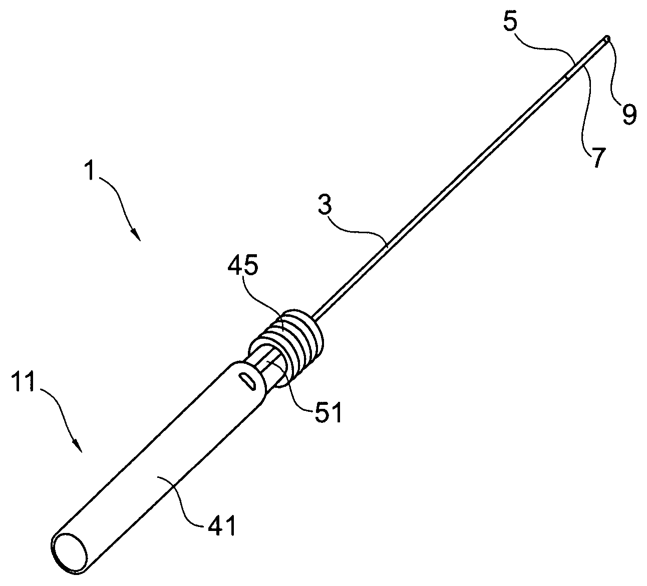
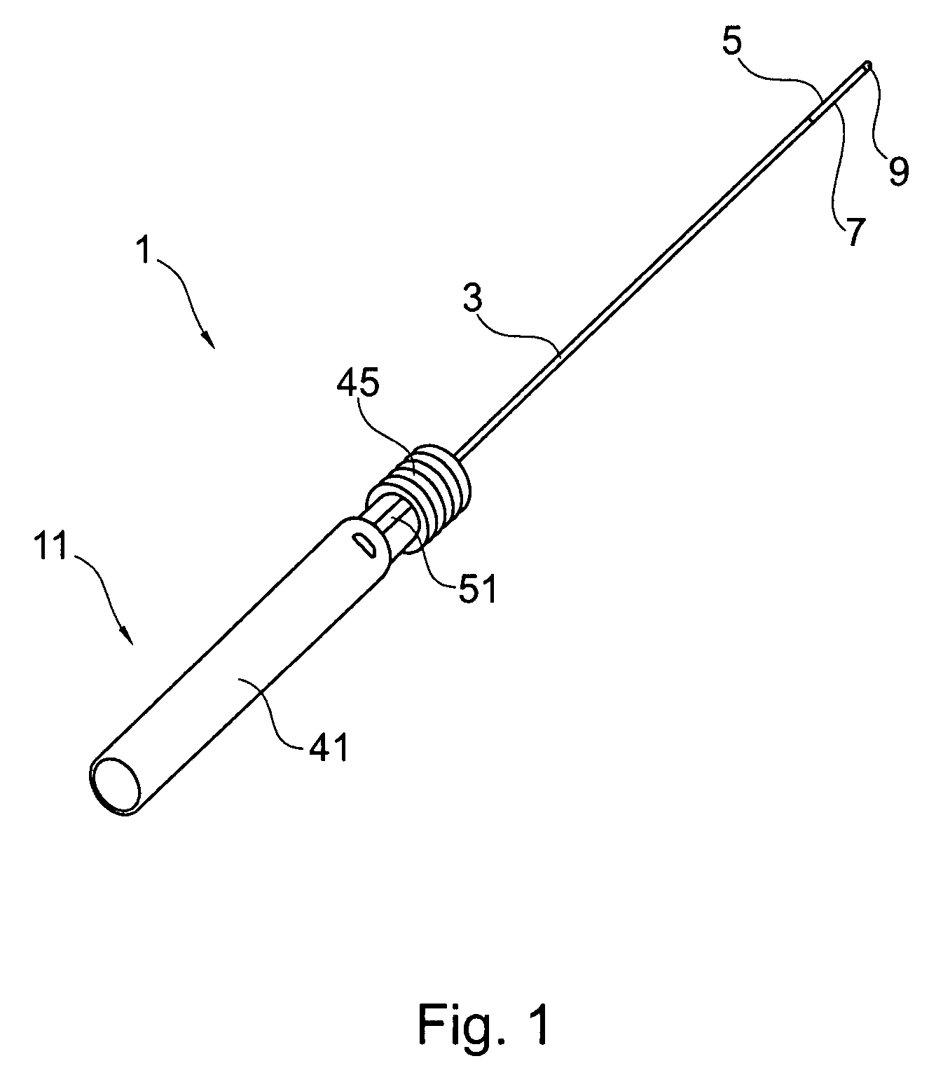
[0039]FIG. 1 schematically shows a preferred measuring device 1 for measuring the length of a through-hole in a bone for example a long bone such as a tibia or femur, including an elongated hollow sleeve 3 with an opening 5 at its distal extremity and a bar or rod 7 having a hook-end 9 at its distal extremity. The measuring device 1 further comprises a handle 11 including a rotatable grip 41, a static part 45 and a scale 51, wherein the rotatable grip 41 is adapted for displacing the bar or rod 7 longitudinally along sleeve 3.

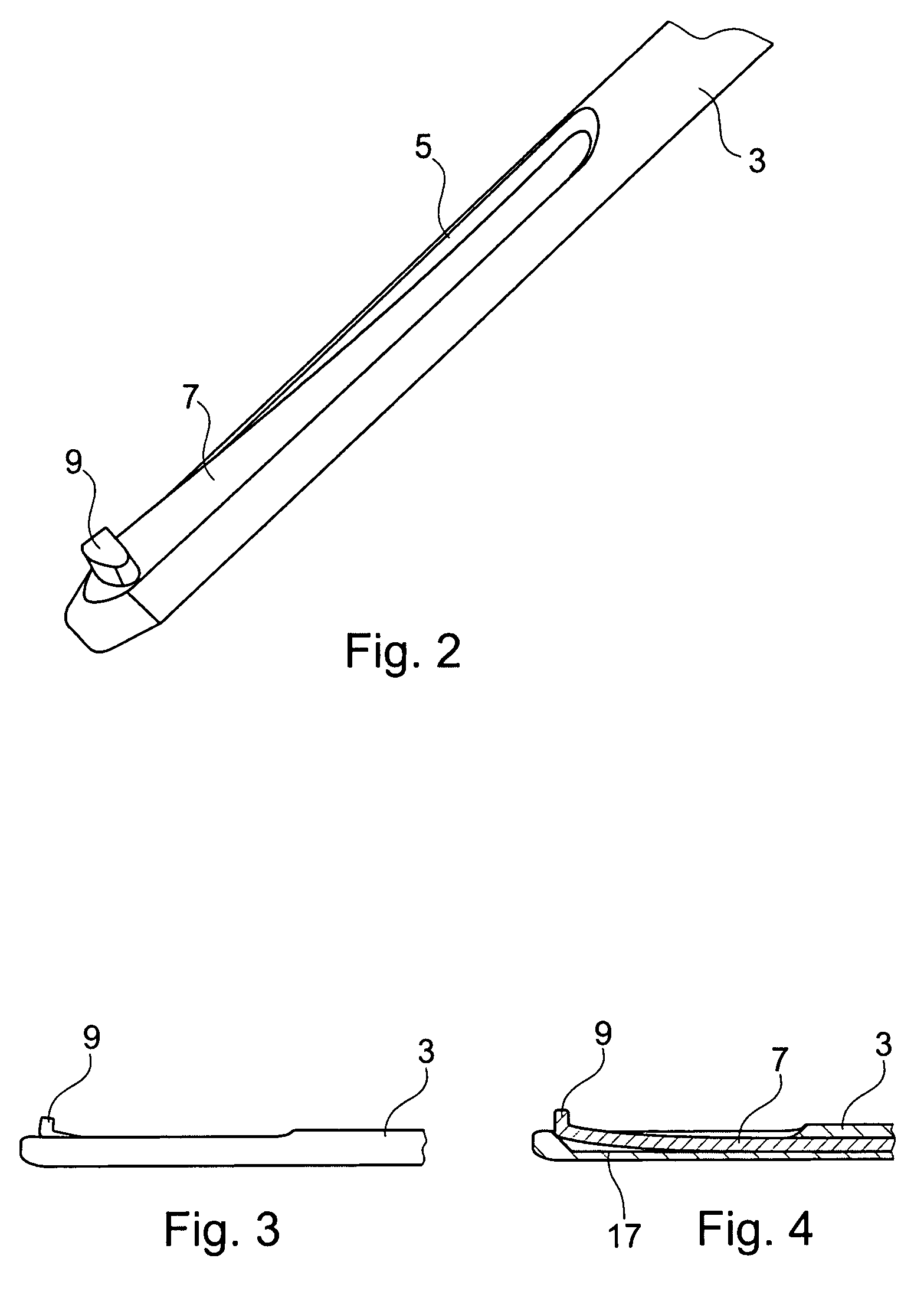
[0040]As can be seen from FIGS. 2, 3 and 4, the distal extremity of preferred sleeve 3 comprises an opening 5 in the form of an elongated slot in the lateral surface of sleeve 3. In the preferred embodiment the opening 5 has a width corresponding to the width of rod 7 housed within sleeve 3 such that rod 7 can deflect out of sleeve 3 through opening 5 at the distal part of sleeve 3.

[0041]In a distal position where rod 7 is pushed towards the distal extremity of...


PUM


Abstract

A measuring device for measuring the length of a through-hole in a bone has an elongated hollow sleeve preferably having an outer cross-section adapted to a cross-section of the through-hole and having an opening at its distal extremity. The measuring device further comprises a rod having a hook-shaped end at its distal extremity. The rod is at least partly housed within the hollow sleeve and is slidable with respect to the sleeve along its longitudinal axis. The sleeve and the rod are designed such that, when the rod is slid to a distal position of the sleeve, the hook-end can be displaced such as to protrude through the opening of the sleeve and laterally over the lateral outer surface of the sleeve. When the rod is slid to a proximal position of the sleeve, the rod no longer protrudes laterally over the outer surface of the sleeve.

Description

BACKGROUND OF THE INVENTION[0001]The present invention relates to a measuring device and to a measuring kit for measuring a length of a through-hole in a bone, such as a long bone, for example, a femur, tibia and humerus.[0002]It is known, for example, in osteosynthesis, to provide a connection between an implant and a bone by elongated fixing elements such as screws. The fixing element may be inserted into the bone bicortically i.e. the fixing element extends into or through both cortex-parts at opposing surfaces of the bone. A through-hole through the bone having a diameter corresponding to the core diameter of the screw to be used for fixing the implant to the bone is usually drilled before inserting the screw. For this purpose, a hollow protection sleeve may be inserted through the patient's soft tissue surrounding the bone until it abuts the bone. Then, a drill may be inserted through the protection sleeve and may drill the through-hole into the bone.[0003]After pre-drilling th...

Claims


Application Information

Patent Timeline
Patent Type & Authority Applications(United States)
IPC IPC(8): A61B17/58
CPCA61B5/1076A61B5/4504G01B3/08A61B2019/461A61B2019/462A61B19/46A61B90/06A61B2090/061A61B2090/062G01B3/28
Inventor PRIEN, OLEGIERSCH, HELGE
Owner STRYKER TRAUMA GMBH
Why Eureka
Try Eureka