Vascular Suturing Device

Active Publication Date: 2009-01-01
ABBOTT LAB INC
View PDF14 Cites 98 Cited by
  • Summary
  • Abstract
  • Description
  • Claims
  • Application Information

AI Technical Summary

Benefits of technology

[0012]In another form, the present invention provides a method of suturing vascular tissue adjacent an opening in a vascular vessel. The method uses a suturing device which can be inserted through the opening in the vascular vessel. The device comprises: a proximal member with a needle channel formed therein; a distal member configured to be inserted into the lumen of the vascular vessel, where the distal member has a receptacle that includes a needle capture element and which is sized to receive at least one needle; and an intermediate member disposed between the proximal member and the distal member. The intermediate member defines a tis

Problems solved by technology

Closing the wound can be difficult because of the substantial bleeding that can occur through an open wound in the vascular vessel.
This approach suffers from many deleterious effects, not the least of which are that it can be time consuming and extremely uncomfortable—even painful—for the patient because the pressure is applied directly on or adjacent to the traumatized site.
During this initial recovery period, it is imperative that the patient remain still, further adding to the patient's discomfort.
This can be extremely difficult because the vascular vessel with the puncture lies underneath the patient's outer skin.
Some vascular vessels, notably the femoral artery, appear to be relatively large; however, in practice, even the largest arteries cannot be readily sutured.
Some complications

Method used


Image

  • Vascular Suturing Device
  • Vascular Suturing Device
  • Vascular Suturing Device

Examples


Embodiment Construction

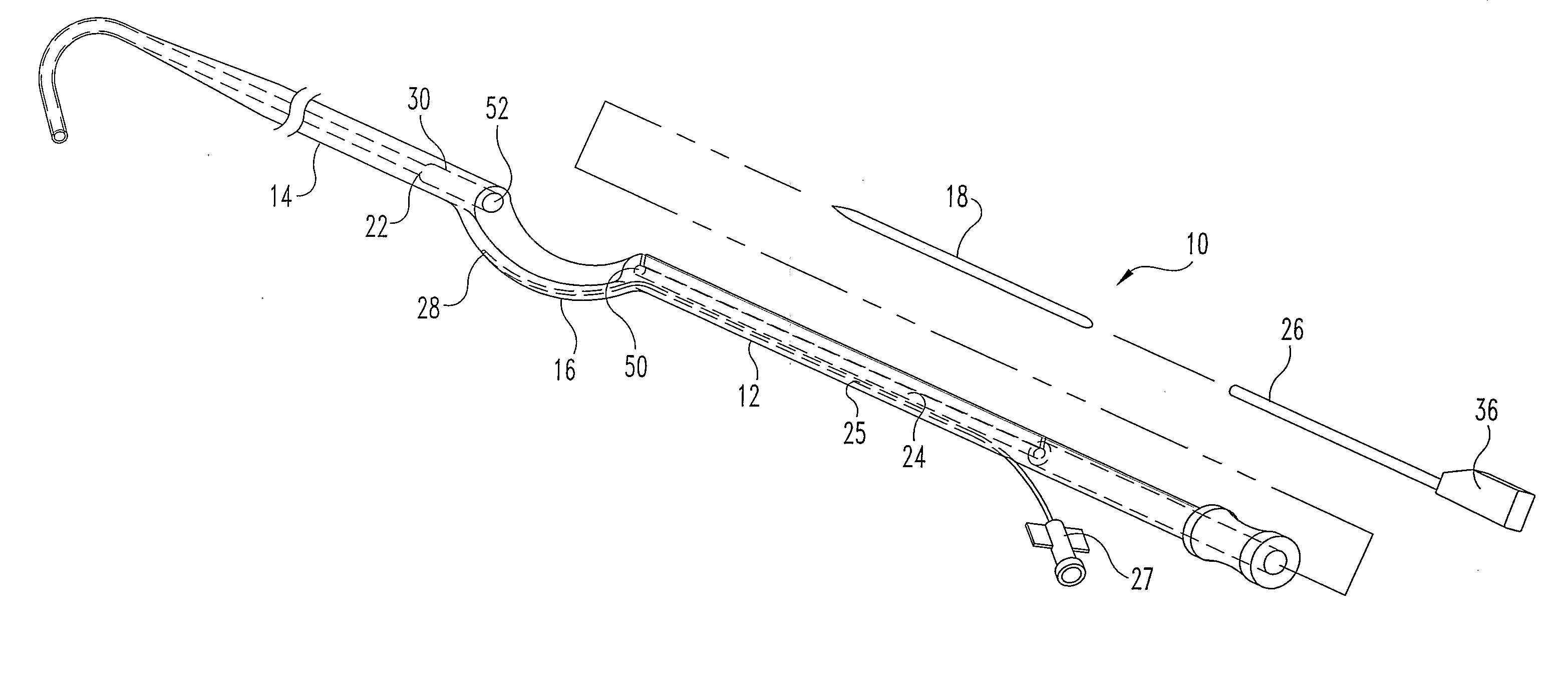
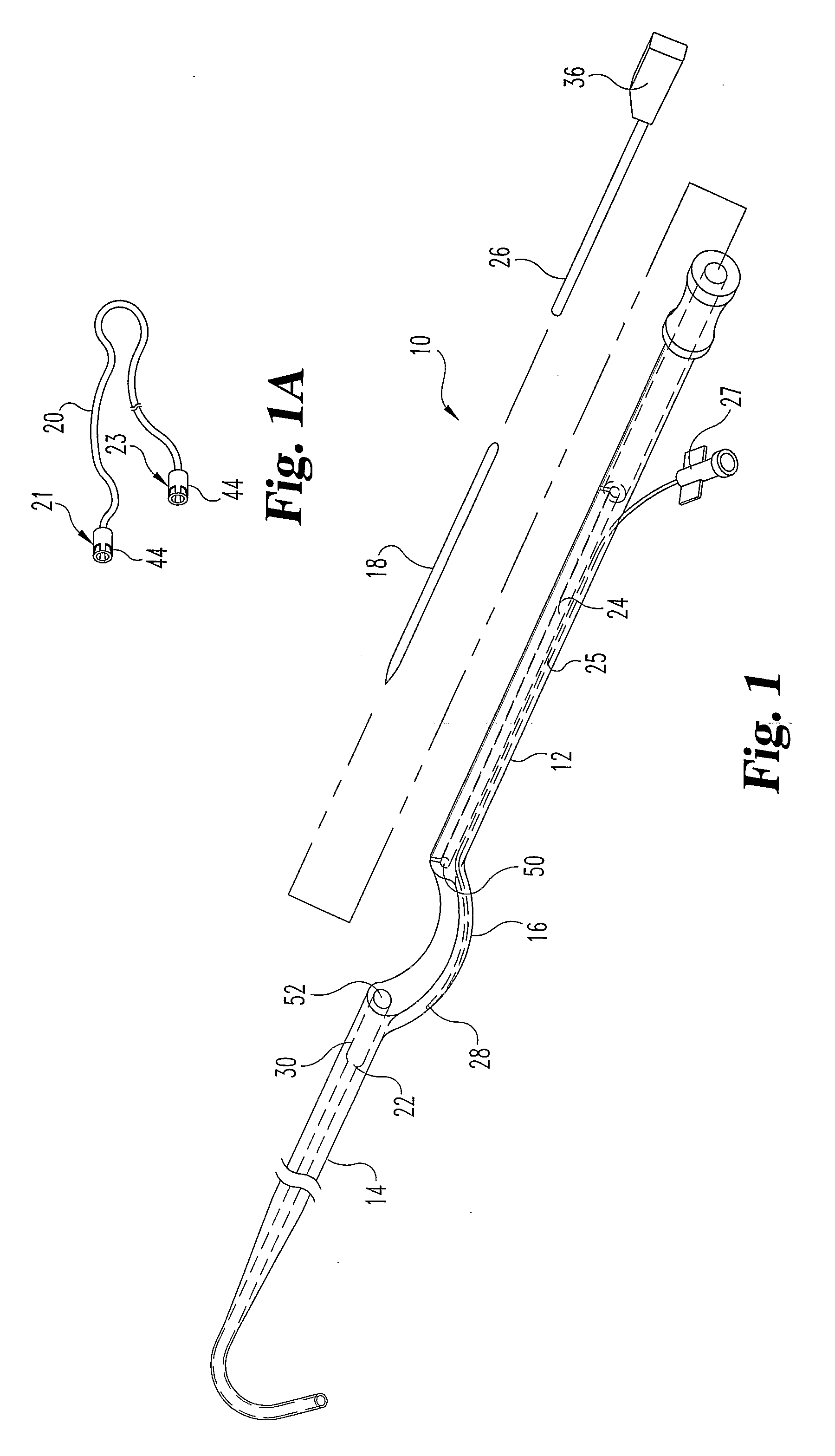
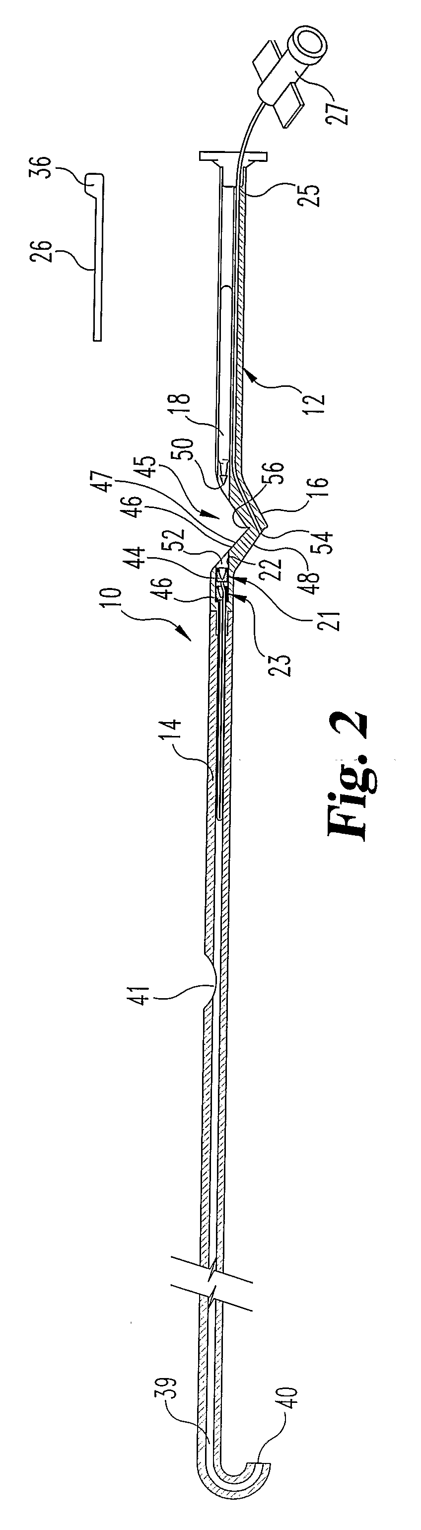
[0049]FIG. 1 is an exploded view of one embodiment of a suturing device 10 for suturing vascular vessels in accordance with the present invention. Device 10 includes a proximal member 12, a distal member 14, and an intermediate member 16 located therebetween. Device 10 includes one or more needles 18 advanceable through a portion of the proximal and distal members. A needle pusher 26 can either push or engage needle 18 to advance it through a channel 24 in the proximal member and through vascular tissue adjacent the puncture wound. In one form, suture material can be attached to needle 18 which is then advanced in a distal direction through tissue. In other forms, suture material can be located within distal member to be snared by a needle to be withdrawn in a proximal direction through tissue. A second needle and subsequent needles can be similarly configured and manipulated to place sutures through tissue adjacent a puncture wound in a vascular vessel. The suture material(s) threa...


PUM


Abstract

A surgical device of suturing vascular vessels is described, as well as methods for suturing tissue employing the surgical device. In one form the device includes a distal member for insertion into a vascular vessel puncture wound. The distal member contains a suture and needle engaging fitting. At least one needle is advanced through tissue adjacent the puncture wound and into the needle engaging fitting to draw lengths of suture material which can then be used to close the puncture wound. In another form the device includes at least one needle advanceable through tissue and into a needle capture element within a distal end of the surgical device to draw lengths of suture material which can then be used to close various puncture wounds, particularly in vascular tissue. In still another form the device includes at least one needle advanceable through tissue to drawn lengths of suture material which can then be used to close various puncture wounds, particularly in vascular tissue. A foot is pivotal between a non-deployed position and a deployed position where it engages vascular tissue on a distal side of the vessel.

Description

BACKGROUND OF THE INVENTION[0001]The present invention generally relates to surgical instruments and methods of suturing tissue.[0002]A number of diagnostic and treatment procedures are conducted intravascularly. Typically, a catheter is introduced into the vascular system at a convenient access location and is then guided to the target treatment site. The Seldinger Technique is one of the well-known early examples of this type of procedure which can include catheterization and angioplasty techniques. Procedures such as this require a vascular access. Typically an introducer sheath with or without a guide wire is inserted through a puncture wound in a vessel such as the femoral artery at a location near the groin. A catheter and other instrumentation can then be inserted through the sheath and guided to the targeted treatment site. After the diagnostic and / or treatment procedure has been completed, the puncture wound must be closed. Closing the wound can be difficult because of the ...

Claims


Application Information

Patent Timeline
IPC IPC(8): A61B17/04
CPCA61B17/0057A61B17/0469A61B17/0482A61B17/0487A61B17/06004A61B2017/06028A61B2017/00637A61B2017/00663A61B2017/0454A61B2017/0464A61B2017/06009A61B17/0625
Inventor PANTAGES, ANTHONY J.ELLINGWOOD, BRIAN A.WALBERG, ERIK K.
Owner ABBOTT LAB INC
Why Eureka
Try Eureka