Flexible Spine Stabilization System

a stabilization system and flexible technology, applied in the field of flexible stabilization systems, can solve the problems of accelerating degeneration of the spine, irreversible procedure, further injury to other parts of the spine,

Active Publication Date: 2009-01-01
GLOBUS MEDICAL INC
View PDF104 Cites 205 Cited by
  • Summary
  • Abstract
  • Description
  • Claims
  • Application Information

AI Technical Summary

Benefits of technology

[0013]Another embodiment is directed towards a device for intervertebral or intersegmental stabilization designed to ensure proper alignment and motion between vertebrae of the spinal column that helps partially unload the discs and facet joints to give pain relief.

Problems solved by technology

Components of a motion segment that move out of position or become damaged can lead to serious pain and may lead to further injury to other components of the spine.
Underlying causes of structural changes in the motion segment unit leading to instability include trauma, degeneration, aging, disease, surgery, and the like.
There are several disadvantages to fusion, however.
In addition to a loss of mobility, fusion also causes the mobility of the motion segment to be transferred to other motion segments of the spine.
The added stresses transferred to motion segments neighboring or nearby the fused segment can cause or accelerate degeneration of those segments.
One other disadvantage to fusion is that it is an irreversible procedure.
In addition, it is believed that fusion of a motion segment has a clinical success of approximately 70 percent, and often does not alleviate pain experienced by the patient.
Thus, while such fusion systems have been used since the early 1960's, the intentionally rigid designs have often caused stress concentrations and have directly and indirectly contributed to the degeneration of the joints above and below the fusion site (as well as at the fusion site itself).
Finally, removal of portions of the motion segment unit reduces the amount of support available for the affected motion segment unit.

Method used


Image

  • Flexible Spine Stabilization System
  • Flexible Spine Stabilization System
  • Flexible Spine Stabilization System

Examples


Embodiment Construction

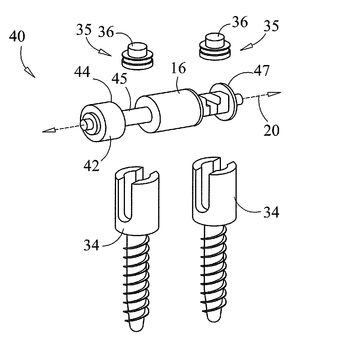
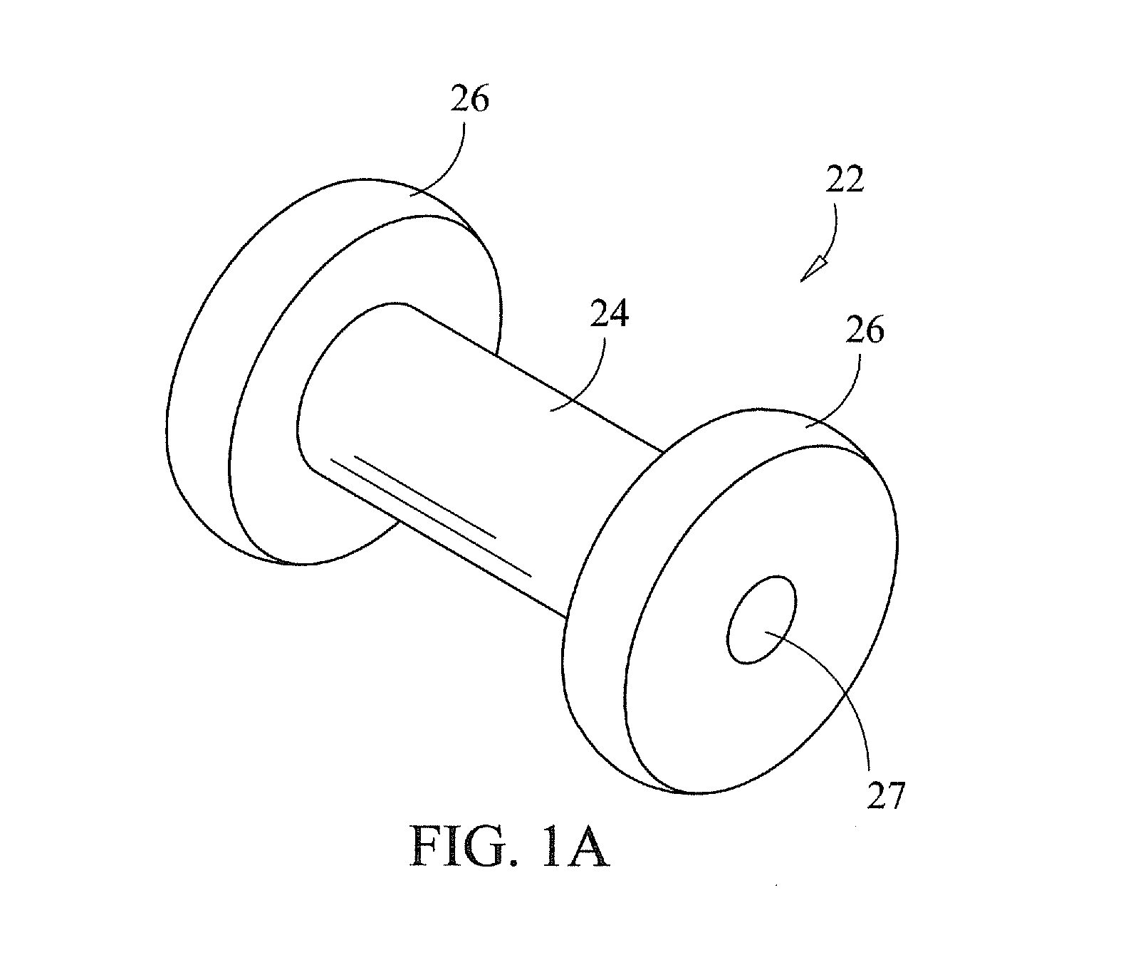
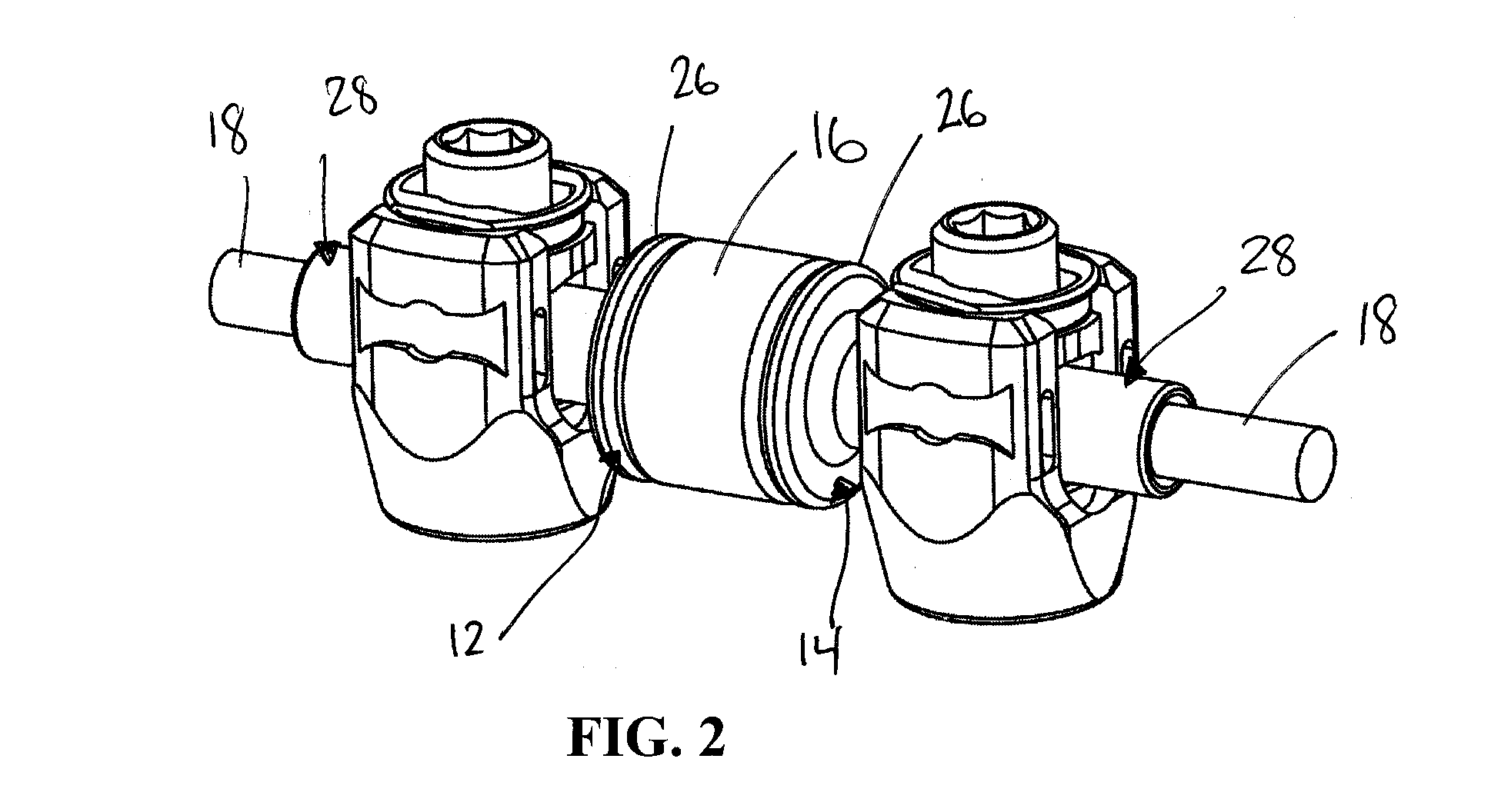
[0059]Embodiments of the disclosure are generally directed to flexible stabilization systems for use with the anterior, antero-lateral, lateral, and / or posterior portions of at least one motion segment unit of the spine. The systems of the invention are designed to be conformable to the spinal anatomy, so as to be generally less intrusive to surrounding tissue and vasculature than existing rigid stabilization systems.

[0060]Certain embodiments may be used on the cervical, thoracic, lumbar, and / or sacral segments of the spine. For example, the size and mass increase of the vertebrae in the spine from the cervical to the lumbar portions is directly related to an increased capacity for supporting larger loads. This increase in load bearing capacity, however, is paralleled by a decrease in flexibility and an increase in susceptibility to strain. When rigid immobilization systems are used in the lumbar segment, the flexibility is decreased even further beyond the natural motion restrictio...


PUM


Abstract

A system for flexibly stabilizing a vertebral motion segment by connecting a first vertebra and a second vertebra is disclosed. The system includes an elongate connection element with end portions interconnected by a flexible coupling member. The system includes first and second attachment portions for connecting the connection element to the vertebrae. A first resilient member is positioned between the first end portion and the first attachment portion, and a second resilient member is positioned between the first attachment portion and the second attachment portion. The system is designed such that the second resilient member is compressed when the first and second attachment portions move towards each other, and the first resilient member is compressed when the first and second attachment portions extend away from each other.

Description

CROSS-REFERENCE TO RELATED APPLICATIONS[0001]This application claims priority to U.S. Provisional Application Ser. No. 60 / 914,993 filed on Apr. 30, 2007, which is incorporated herein by reference in its entirety.FIELD OF THE INVENTION[0002]The present disclosure generally relates to flexible stabilization systems for spinal motion segment units. In particular, certain embodiments are directed to a soft stabilization system including at least two bone fasteners and a flexible portion conformable to the natural spinal movement.BACKGROUND OF THE INVENTION[0003]The spine includes a series of joints routinely called motion segment units, which is the smallest component of the spine that exhibits kinematic behavior characteristic of the entire spine. The motion segment unit is capable of flexion, extension, lateral bending and translation. The components of each motion segment unit include two adjacent vertebrae and their apophyseal joints, the intervertebral disc, and the connecting liga...

Claims


Application Information

Patent Timeline
Patent Type & Authority Applications(United States)
IPC IPC(8): A61B17/70A61B17/04
CPCA61B17/7007A61B17/7031A61B17/702A61B17/7008A61B17/7001A61B17/7019A61B17/7049A61B17/7052
Inventor FRIEDRICH, ADAMIOTT, ANDREWKARPOWICZ, EDWARD
Owner GLOBUS MEDICAL INC
Why Eureka
Try Eureka