
Vehicle navigation systems and methods

a vehicle navigation and vehicle technology, applied in the field of vehicle navigation, can solve the problems of discrepancy between the actual position of the vehicle and the navigation position, and achieve the effect of enhancing the navigation accuracy

Inactive Publication Date: 2009-01-01
HON HAI PRECISION IND CO LTD
View PDF10 Cites 35 Cited by
  • Summary
  • Abstract
  • Description
  • Claims
  • Application Information

AI Technical Summary

Benefits of technology

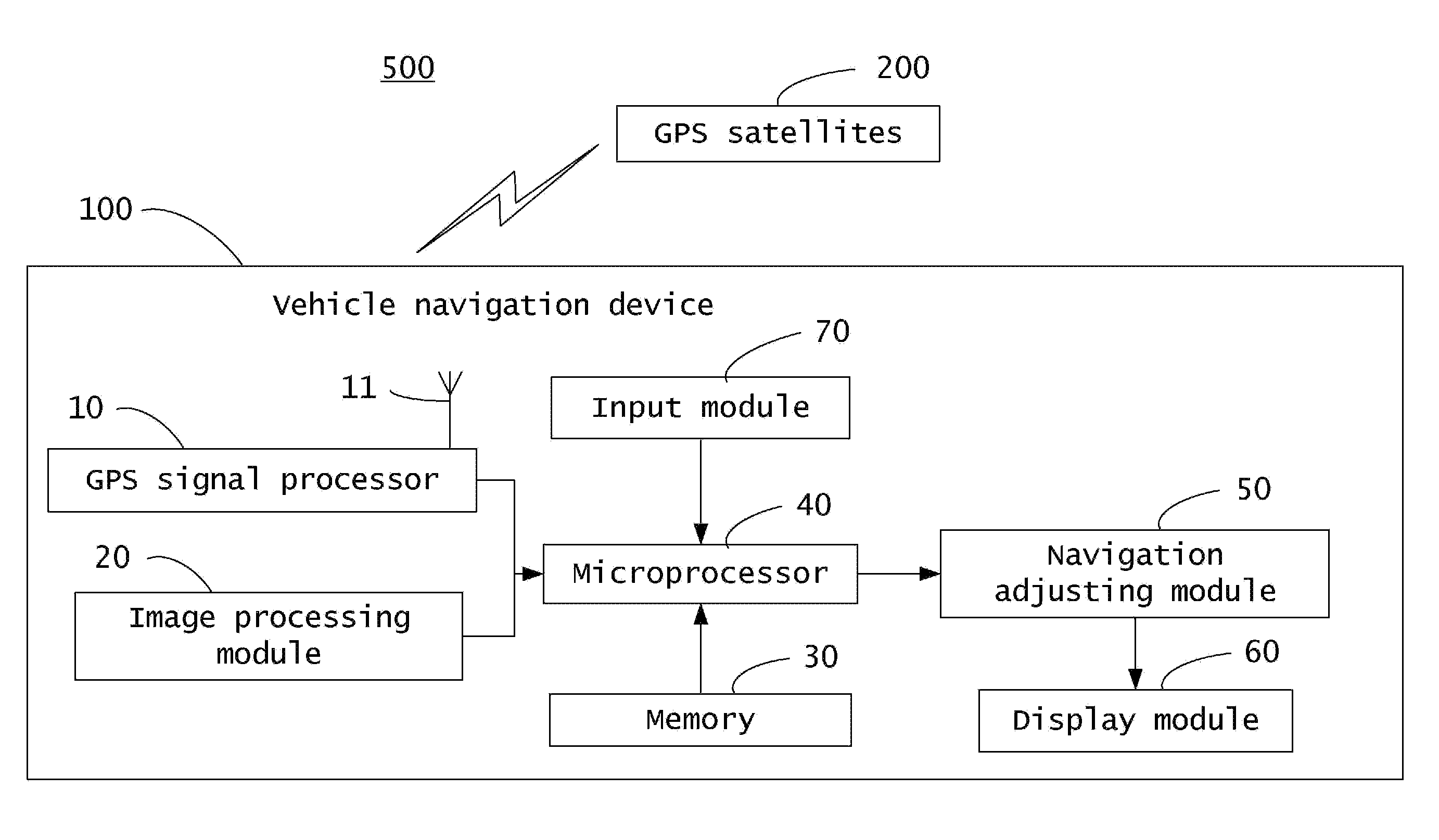
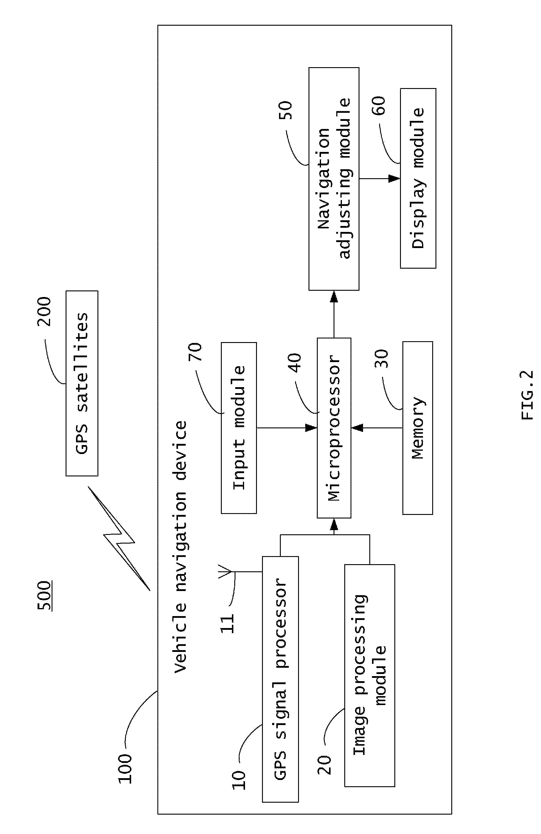
[0009]Accordingly, a vehicle navigation system is provided for enhancing navigation accuracy. The vehicle navigation system comprises a GPS signal processor, an image processing module, a memory, a microprocessor, a navigation adjusting module and a display module. The GPS signal processor is used for receiving GPS signals and obtaining an unadjusted navigation position according to the GPS signals. The image processing module is used for capturing a plurality of pictures of an area surrounding a vehicle and acquiring a reference position according to the plurality of pictures. The memory is used for storing a predetermined offset between the reference position and the unadjusted navigation position. The microprocessor is used for calculating an offset between the reference position and the unadjusted navigation position and comparing the offset with the predetermined offset, wherein the microprocessor determines an adjustment signal upon the condition that the offset is larger than or equal to the predetermined offset. The navigation adjusting module is used for adjusting the unadjusted navigation position according the adjustment signal into an adjusted navigation position. The display module is used for displaying the adjusted navigation position on an electronic map. A vehicle navigation method is also disclosed.

Problems solved by technology

However, when the vehicle 99′ travels in an area when the GPS signal is weak, such as in a tunnel, then the discrepancy between the navigation position and the actual position of the vehicle 99′ is often not within an acceptable range.

Method used


Image

  • Vehicle navigation systems and methods
  • Vehicle navigation systems and methods
  • Vehicle navigation systems and methods

Examples


Embodiment Construction

[0016]Reference will now be made to the drawings to describe certain inventive embodiments of the present disclosure.

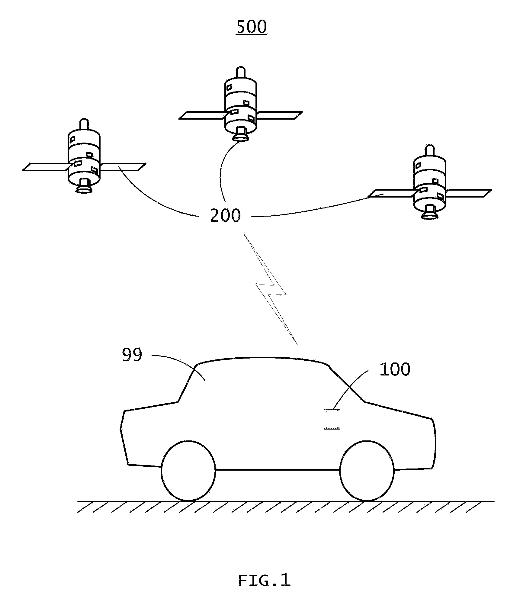
[0017]Referring to FIGS. 1 and 2, a vehicle navigation system 500 in accordance with one embodiment of the present disclosure includes a navigation device 100 disposed in a vehicle 99, and GPS satellites 200 for transmitting GPS signals to the navigation device 100.

[0018]The navigation device 100 includes a GPS signal processor 10, an image processing module 20, a memory 30, a microprocessor 40, a navigation adjusting module 50, a display module 60, and an input module 70.

[0019]The GPS signal processor 10 receives the GPS signals transmitted by the GPS satellites 200 via an antenna 11, and obtains an unadjusted navigation position Sn+1(Xn+1, Yn+1, Zn+1) of the vehicle 99 according to the GPS signals. It may be understood that a subscript “n” of the equation Sn+1(Xn+1,Yn+1, Zn+1) represents a natural number, such as, n=0, 1, 2, . . . , for example. The equation Sn+1(Xn...


PUM


Abstract

A vehicle navigation system includes a GPS signal processor, an image processing module, a memory, a microprocessor, a navigation adjusting module, and a display module. The GPS signal processor receives GPS signals and obtains an unadjusted navigation position according to the GPS signals. The image processing module captures pictures of surrounding areas and acquires a reference position according to the pictures. The microprocessor calculates an offset between the reference position and the unadjusted navigation position and compares the offset with a predetermined offset. The navigation adjusting module adjusts the unadjusted navigation position according to the reference position and the offset comparison and displays a result on the display module.

Description

BACKGROUND[0001]1. Field of the Invention[0002]Embodiments of the present disclosure generally relate to vehicle navigation, and more particularly to systems and methods for navigating a vehicle.[0003]2. Description of Related Art[0004]Referring to FIG. 5, a global positioning system (GPS) navigation device 100′ is used to navigate a vehicle 99′ to a predetermined destination. Typically, the navigation device 100′ includes a GPS signal processor, a display module, and a memory for storing an electronic map.[0005]The GPS signal processor receives GPS signals transmitted by GPS satellites 200′, and obtains a first navigation position S1′ and a second navigation position S2′ according to the GPS signals. The first navigation position S1′ corresponds to a first actual position S1 of the vehicle 99′, while the second navigation position S2′ corresponds to a second actual position S2 of the vehicle 99′. The vehicle 99 sequentially travels from the first actual position S1 to the second ac...

Claims


Application Information

Patent Timeline
Patent Type & Authority Applications(United States)
IPC IPC(8): G01C21/34G01C21/00G01S5/00G01S19/48
CPCG01C21/28
Inventor CHUNG, WEN-HUNGHSU, YING-HAOYANG, FU-CHI
Owner HON HAI PRECISION IND CO LTD
Learn More