

Cyclonic separating apparatus
a technology of cyclonic separation and separating apparatus, which is applied in the direction of filter regeneration, liquid separation agent use, dispersed particle filtration, etc., can solve the problem of a large amount of dirt and dust passing through the shroud
- Summary
- Abstract
- Description
- Claims
- Application Information
AI Technical Summary
Benefits of technology
Problems solved by technology
Method used
Image

Examples
Embodiment Construction
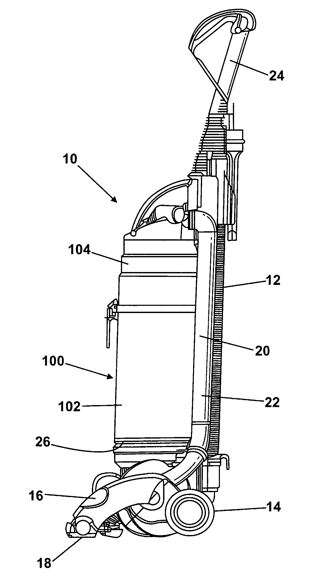
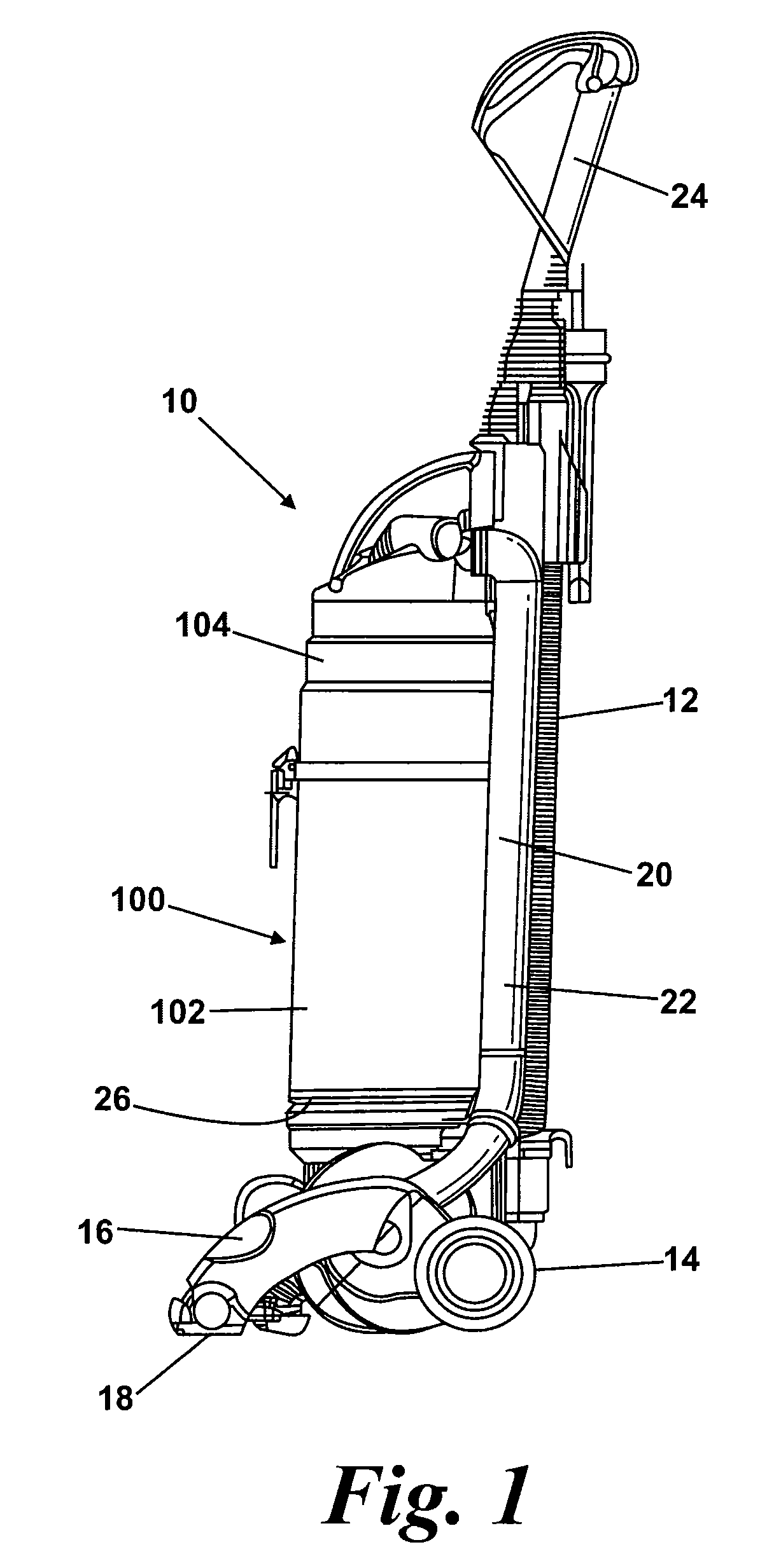
[0029]FIG. 1 shows an upright vacuum cleaner 10 having a main body 12 which includes a motor and fan unit (not shown) and a pair of wheels 14. A cleaner head 16 is pivotably mounted on the lower end of the main body 12 and a dirty air inlet 18 is provided in the underside of the cleaner head 16 facing the floor surface. The main body 12 further includes a spine 20 which extends vertically upward and includes ducting 22 for carrying an airflow. A handle 24 is formed at the upper end of the spine 20. The handle 24 can be manipulated by a user to manoeuvre the vacuum cleaner 10 across a floor surface. The handle 24 is also releasable in the manner of a wand to allow above the floor cleaning. This feature is not material to the present invention and will not be described any further here. The main body 12 further includes a plurality of outlet ports 26 for exhausting air from the vacuum cleaner 10.
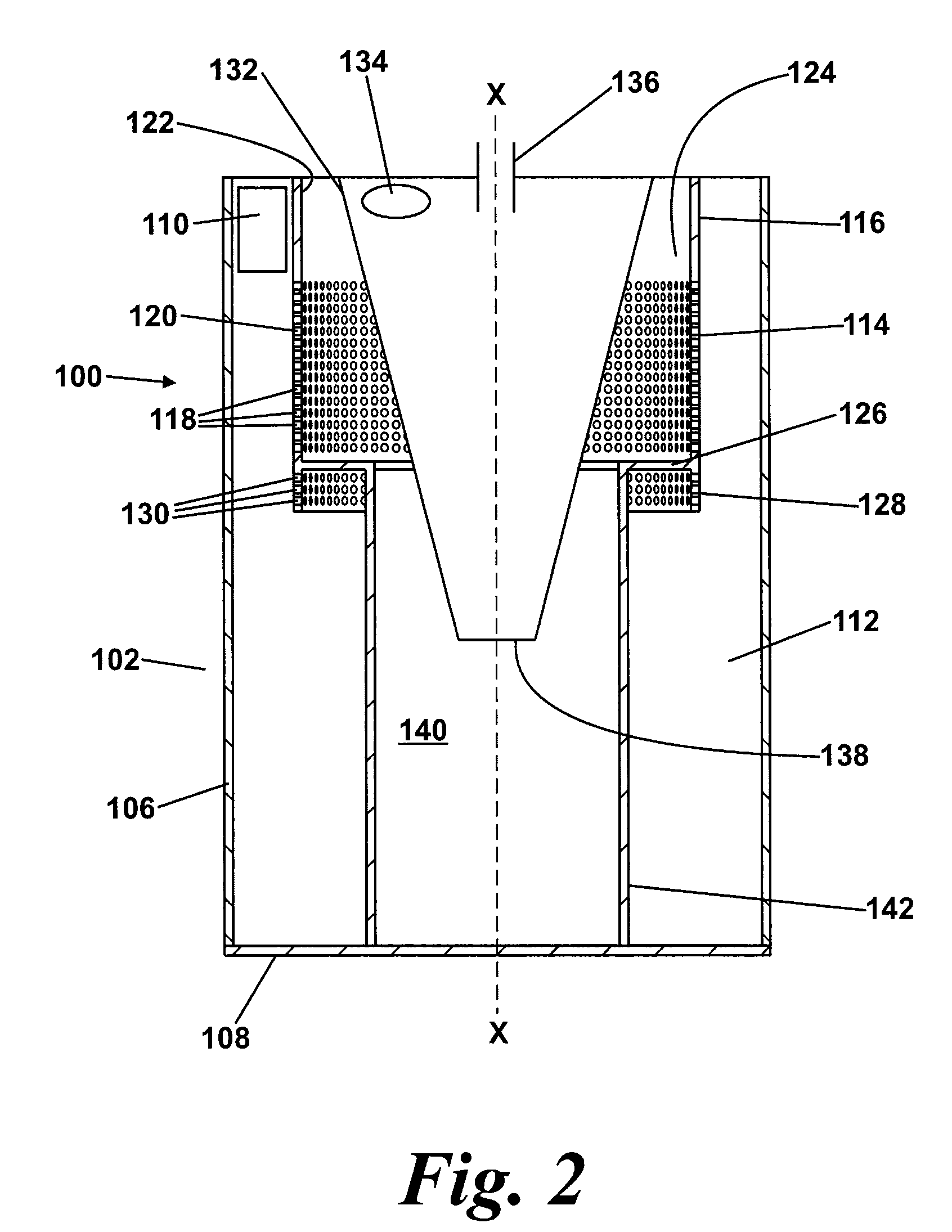
[0030]The vacuum cleaner 10 further comprises cyclonic separating apparatus 100. The cyclo...
PUM
| Property | Measurement | Unit |
|---|---|---|
| angle | aaaaa | aaaaa |
| angle | aaaaa | aaaaa |
| height | aaaaa | aaaaa |
Abstract
Description
Claims
Application Information