Method and apparatus for shaping a magnetic field in a magnetic field-enhanced plasma reactor

a plasma reactor and magnetic field technology, applied in the direction of spraying apparatus, spray discharge apparatus, coatings, etc., can solve the problems of non-uniform electron density across, major source of damage to semiconductor devices, and exb drift of free electrons, so as to improve the shaping of the magnetic field gradient and the effect of greater control over the shape of the magnetic field

Inactive Publication Date: 2009-01-08
APPLIED MATERIALS INC
View PDF50 Cites 1 Cited by
  • Summary
  • Abstract
  • Description
  • Claims
  • Application Information

AI Technical Summary

Benefits of technology

[0020]The disadvantages associated with the prior art are overcome by a method and apparatus of providing improved shaping of the magnetic field gradient within a magnetically enhanced plasma reactor to produce a uniform plasma. Generally, the invention uses a plurality of overlapping main magnetic coil sections for forming a magnetic field generally parallel to a top surface of a substrate supporting member. The overlapping magnetic coils produce a magnetic field having a shape that is improved over the prior art. In other embodiments of the invention, sub-magnetic coils are used in conjunction with the main magnetic coils (whether overlapping or not) to provide greater control over the shape of the magnetic field. Such field control can be used to provide an optimal shape to the instantaneous magnetic field as well as a nearly continuous field shape during the transitions as the magnetic field is rotated.

Problems solved by technology

Despite this advantage, many plasma chambers in commercial use do not employ magnetic enhancement because the magnetic enhancement has been found to increase the likelihood of damaging the semiconductor devices on the wafer.
Such damage is caused by non-uniform electron density across a wafer due to the spatial contour of the magnetic field being poorly optimized.
It is believed that the ExB drift of free electrons is a major source of semiconductor device damage in conventional magnetically enhanced plasma chambers.
Specifically, it is believed that ExB drift can unevenly distribute the free electrons in the plasma pre-sheath and cause non-uniformity in the ion flux.
It is believed that this spatial non-uniformity of the ion flux that bombards the wafer produces electrical currents in the wafer which often damages the semiconductor devices on the wafer.
However, rotating the magnetic field does not in any way improve the instantaneous spatial uniformity of ion flux on the wafer surface, and therefore does not completely solve the problem of semiconductor device damage in magnetically enhanced plasma chambers.
Such a “jump” forms a discontinuity in the plasma process that can damage the substrate or cause non-uniform processing.

Method used


Image

  • Method and apparatus for shaping a magnetic field in a magnetic field-enhanced plasma reactor
  • Method and apparatus for shaping a magnetic field in a magnetic field-enhanced plasma reactor
  • Method and apparatus for shaping a magnetic field in a magnetic field-enhanced plasma reactor

Examples


Embodiment Construction

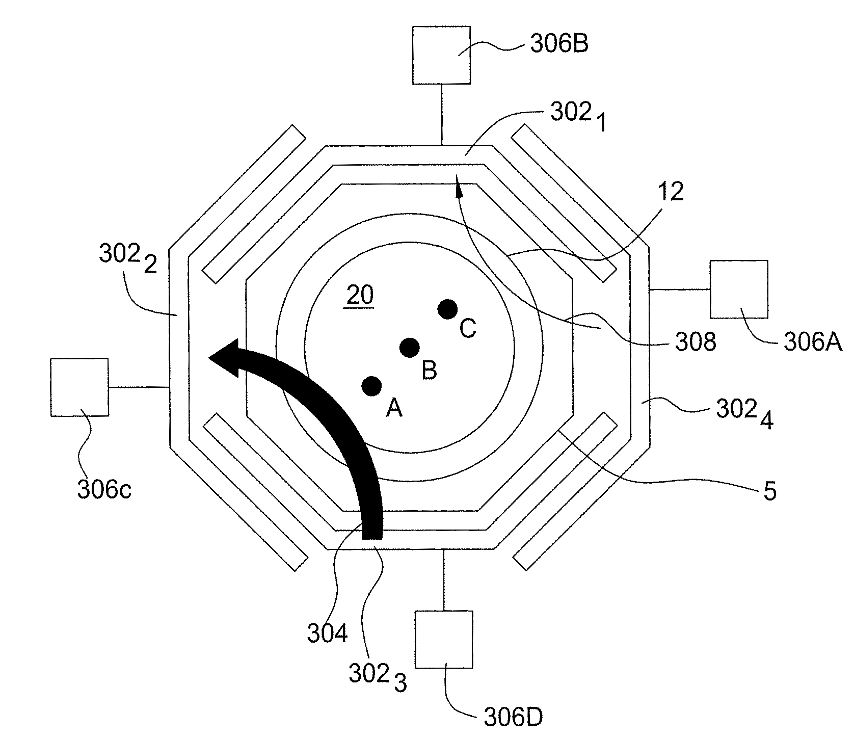
[0039]FIG. 3 is a top view of an embodiment of a magnetic coil configuration 300 circumscribing sidewall 12 of a plasma enhanced chamber 5 in accordance with the present invention. Specifically, FIG. 3 depicts main magnetic coils 3021, 3022, 3023, and 3024 (collectively main magnetic coils 302) and main current sources 306A, 306B, 306C and 306D. As such, in this embodiment of the invention, four coils are driven by four individual currents. Illustratively, the embodiment of the coil configuration 300 is depicted as having a substantially octagonal plan form. However, that depiction is not intended to limit the scope of the invention. For example, a coil configuration in accordance with the invention can be any configuration around the periphery of a chamber 5 with each coil overlapping (or being overlapped by) at least a portion of an adjacent coil.

[0040]Illustratively, each of the main magnetic coils 302 has an extended width such that a portion of each coil overlaps (or is overlap...


PUM

PropertyMeasurementUnit
pressureaaaaaaaaaa
magnetic fieldaaaaaaaaaa
frequencyaaaaaaaaaa

Abstract

A magnetic field generator which provides greater control over the magnetic field is provided. The magnetic field generator has a plurality of overlapping main magnetic coil sections for forming a magnetic field generally parallel to the top surface of the supporting member. In other embodiments, sub-magnetic coil sections are placed symmetrically around the main magnetic coil sections.

Description

CROSS-REFERENCE TO RELATED APPLICATIONS[0001]This application is a continuation of U.S. patent application Ser. No. 10 / 778,933, filed Feb. 3, 2004, by Lindley, et al., and entitled “Method and Apparatus For Shaping A Magnetic Field In A Magnetic Field-Enhanced Plasma Reactor,” which application claims the benefit of the filing date of U.S. Provisional Patent Application Ser. No. 60 / 447,431, filed Feb. 14, 2003, entitled “Method and Apparatus for Producing Plasma Uniformity in a Magnetic Field-Enhanced Plasma Reactor,” each of which is incorporated by reference herein.BACKGROUND OF THE INVENTION[0002]1. Field of the Invention[0003]This invention relates to plasma enhanced, semiconductor substrate processing systems and, more specifically, to a method and apparatus for shaping a magnetic field in a magnetically enhanced plasma reactor.[0004]2. Description of the Related Art[0005]Semiconductor wafer processing chambers commonly employ plasmas to enhance the performance of various proce...

Claims


Application Information

Patent Timeline
Patent Type & Authority Applications(United States)
IPC IPC(8): C23F1/08B05C5/00H01J37/32H01L21/306
CPCH01J37/32623H01J37/32688H01J37/3266
Inventor LINDLEY, ROGER ALANLIU, JINGBAOPU, BRYAN Y.HORIOKA, KEIJI
Owner APPLIED MATERIALS INC
Why Eureka
Try Eureka